Circuit breaker drawer base with self-locking function

A technology of drawer seat and circuit breaker, which is applied in the direction of pull-out switchgear, switchgear, electrical components, etc. It can solve the problems of inability to self-lock and accurately determine the working status of the circuit breaker, and achieve accurate display and simple and convenient operation Effect

Active Publication Date: 2006-01-25
ZHEJIANG CHINT ELECTRIC CO LTD
View PDF0 Cites 21 Cited by
  • Summary
  • Abstract
  • Description
  • Claims
  • Application Information

AI Technical Summary

Problems solved by technology

[0008] The purpose of the present invention is to solve the problem that the drawer seat of the existing drawer type circuit breaker cannot ...

Method used


Image

  • Circuit breaker drawer base with self-locking function
  • Circuit breaker drawer base with self-locking function
  • Circuit breaker drawer base with self-locking function

Examples


Embodiment Construction

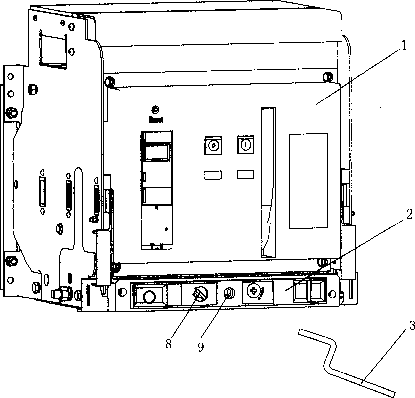
[0038] refer to figure 1 , The circuit breaker 1 is installed in the drawer seat 2, and there are three working positions, namely separation, test and connection. When it is in the separated position, the circuit breaker 1 and the drawer base 2 are completely separated from each other, and the circuit breaker can be pulled out from the drawer base and removed, and the circuit breaker can be inspected, maintained or replaced; when it is in the test position, the circuit breaker 1 Only the secondary circuit is connected with the drawer seat 2, and some action checks can be made on the circuit breaker before it is put into operation; when it is in the connection position, the primary and secondary circuits between the circuit breaker 1 and the drawer seat 2 are completely connected, works fine.

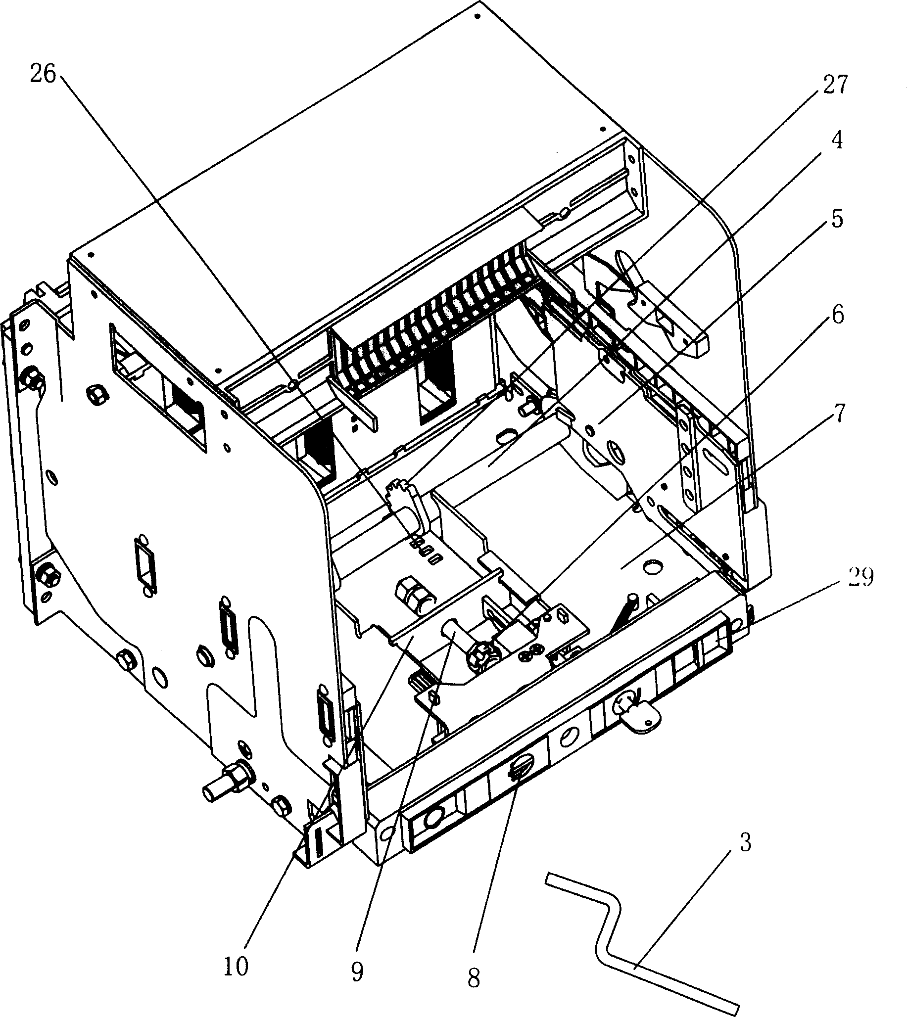
[0039] figure 2 The structural diagram of the drawer seat is shown, and the entire structural diagram can be clearly seen. The circuit breaker 1 is installed on the left and right ma...


PUM


Abstract

This invention discloses a breaker with self-locking function including a base plate, a control panel, a master slide plate, a drive slide, a guide bar, a fixed frame, a screw rod, a slide block, a first crown bar, a second crown bar, a connection bar and a release flat spring. This invention can lock the rotate of a handle to the screw rod when the breaker is at any position of separation, test and connection. De-block and reset is done by rotating the connection bar.

Description

technical field [0001] The invention relates to a drawer seat of a drawer type circuit breaker. The drawer seat can make the circuit breaker enter and exit with three positions of separation, test and connection through the operation of the operating part (handle) on the slider, so as to facilitate the operation of the circuit breaker. Maintenance, isolation and replacement, specifically a circuit breaker drawer seat with self-locking function. Background technique [0002] Among the existing commonly used technologies, the drawer seat of the drawer circuit breaker includes: [0003] ——A pair of main slides arranged on both sides of the drawer seat, linked by the rotating shaft; [0004] - a driving slide, the rear end of which is provided with tooth grooves and engages with gears arranged on said rotating shaft; [0005] - a screw, one end is set on the control panel of the drawer base, and the other is connected to the driving slide; [0006] - a guide rod, the two ends...

Claims


Application Information

Patent Timeline
IPC IPC(8): H02B11/173H02B11/02
Inventor 吴小伟万小东
Owner ZHEJIANG CHINT ELECTRIC CO LTD
Why Eureka
Try Eureka