Steering lock

A locking device and steering shaft technology, which is applied in the application of building locks, vehicle locks, locks, etc., can solve the problems such as hindering the reduction of the number of components of the electric steering locking device 101 and reducing the assembly efficiency of the electric steering locking device 101.

Active Publication Date: 2006-02-01
KK TOKAI RIKA DENKI SEISAKUSHO
View PDF6 Cites 8 Cited by
  • Summary
  • Abstract
  • Description
  • Claims
  • Application Information

AI Technical Summary

Problems solved by technology

[0010] However, the protective cover 129 also becomes a factor hindering the reduction of the number of components of the electric steering lock device 101.
In additio

Method used


Image

  • Steering lock
  • Steering lock
  • Steering lock

Examples


Example

[0038] The assembly of the steering lock device 1 of the first embodiment will be described.

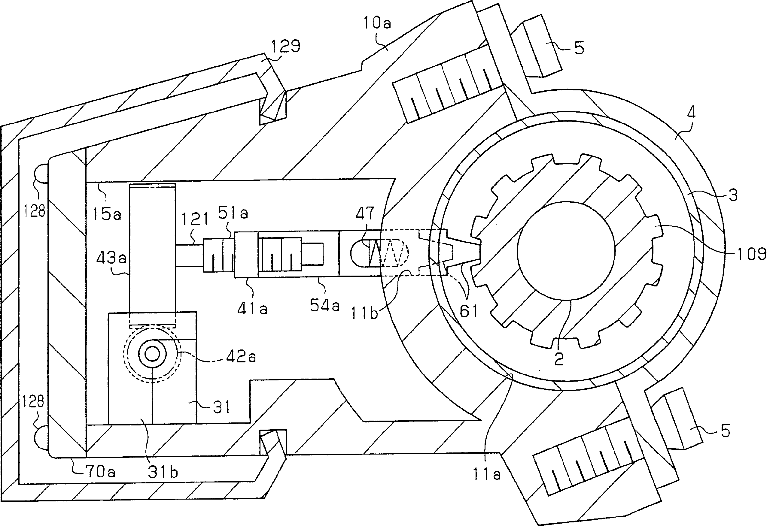
[0039] First, the lock device 30 and the ECU box 110 are installed on the cover 70 to form a lock unit 20. Insert the lock unit 20 into the housing 10 from the opening 15 of the housing 10, and insert the tip of the lock lever 61 into the lock lever passage 11b formed in the housing 10 (refer to Figure 5 )Inside.

[0040] When the cover 70 is positioned by combining the cover 70 with the stepped part 22, the open end surface of the protrusion 93 abuts against the bottom 13 of the recess 12. That is, by positioning the cover 70 with respect to the housing 10, the protrusion 93 is at a designated position inside the housing 10.

[0041] The bolt 6 is inserted into the bolt hole 14 of the recess 12 from the mounting surface 11 side of the housing 10 and screwed with the internal thread 25 of the protrusion 93. In this way, the cover 70 is fixed to the housing 10. Therefore, the head 8 of t...


PUM


Abstract

A steering lock that is easy to assemble but difficult for an automobile thief to dismantle. The steering lock includes a cover on which a support structure for supporting a lock mechanism is integrally formed. The lock mechanism is attached to the cover to assemble a first subunit. A steering lock ECU is attached to an ECU case to assemble a second subunit. The first subunit is attached to the second subunit to assemble a lock unit. The lock unit is attached to the housing. A bolt fastens the lock unit and the housing to each other. A second connector is then attached to the housing.

Description

Technical field [0001] The invention relates to a steering lock device of a vehicle. Background technique [0002] A conventional manual steering lock device is described in Japanese Patent No. 3183588. In the existing manual steering lock device, when the key inserted into the lock core is rotated, the lock lever is hooked with the steering shaft when it is driven by the rotation force. [0003] Japanese Patent Publication (JP-A) 2002-234419, JP-A 2003-063354, JP-A 10-138872, and JP-A 2002-283964 disclose some existing electric steering lock devices. The existing electric steering lock device includes a power device such as a motor that is driven by electricity when the key inserted into the lock core is rotated. The steering shaft is locked by a lock lever driven by the power unit. [0004] FIG. 1 shows a conventional electric steering lock device 101. The steering wheel 106 is mounted on the steering shaft 2. The electric steering lock device 101 includes a sleeve 3, a bearing...

Claims


Application Information

Patent Timeline
IPC IPC(8): B60R25/02B60R25/0215E05B83/00
CPCB60R25/02153Y10T70/5531Y10T70/5664Y10T70/5956
Inventor 长谷川博康奥野正也村上健村上光央
Owner KK TOKAI RIKA DENKI SEISAKUSHO
Why Eureka
Try Eureka