
Pair circuit substrate operating machine

A technology for circuit substrates and operating machines, which is applied to electrical components, electrical components, etc., and can solve problems such as defective circuit substrates

Active Publication Date: 2006-03-22
FUJI KK
View PDF8 Cites 12 Cited by
  • Summary
  • Abstract
  • Description
  • Claims
  • Application Information

AI Technical Summary

Problems solved by technology

In the electronic circuit component mounting machine, the component holder receives the electronic circuit component supplied by the component supply device and mounts it on the printed wiring board. However, for example, the electronic circuit component held by the component holder is not the electronic circuit that should be received. components, or defective products, if they are mounted on printed wiring boards as they are, defective circuit boards will be produced

Method used


Image

  • Pair circuit substrate operating machine
  • Pair circuit substrate operating machine
  • Pair circuit substrate operating machine

Examples


Embodiment Construction

[0091] Hereinafter, an embodiment in which the present invention is applied to an electronic circuit component mounting machine which is a type of circuit board working machine will be described in detail with reference to the drawings.

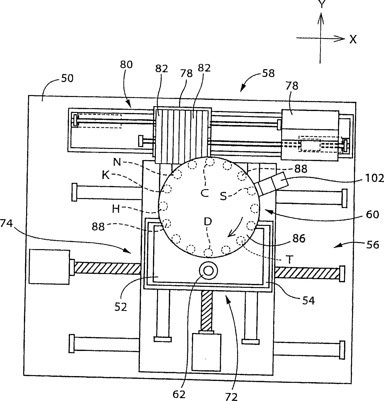
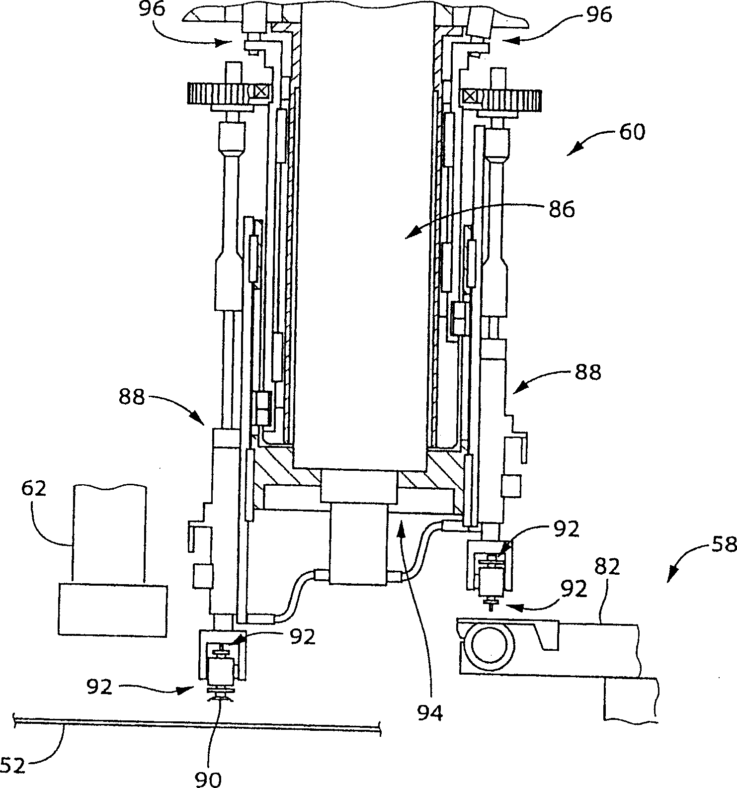
[0092] This electronic circuit component mounting machine is a rotary head type mounting machine having a component mounting device that rotates a plurality of mounting heads around a single rotation axis. figure 1 A plan view showing this electronic circuit component mounting machine, figure 2 It shows a side partial sectional view centering on the component mounting device included in this electronic circuit component mounting machine.

[0093] This electronic circuit component mounting machine, such as figure 1 As shown, it is mainly composed of the following parts: a working machine body 50; a wiring board fixing device 54 arranged on the working machine body 50 to fix a printed wiring board 52 as a circuit substrate as a substrate hold...


PUM


Abstract

In a pair circuit substrate operating machine, a part of an image picked up by an image pickup device is selected and displayed without requiring operation by an operator. An adsorption nozzle receives an electronic circuit part from a feeder at the part reception position. After this a part camera performs imaging to acquire a holding position error. The error is corrected, and the image is mounted on a printed circuit board. If an image processing results in an error and the error occurrence ratio exceeds a set ratio, a display condition is set (S7 to S13 and the like). The display condition is set manually by the operator or automatically by a computer. At least one of the part type, the adsorption nozzle, and the feeder should be identical to the part type which has caused the error, the adsorption nozzle holding the part, and the feeder which has supplied the part. After the condition is set, image data of the image matched with the condition is stored in a memory regardless of the presence / absence of an error and displayed on the display screen, so that the operator analyzes the error cause (S32 to S38).

Description

technical field [0001] The present invention relates to a circuit board handling machine for performing predetermined work on circuit boards such as printed wiring boards, and more particularly to a circuit board working machine for imaging a predetermined object with an imaging device and displaying it on a display device. Background technique [0002] As circuit board working machines, there is an electronic circuit component mounting machine for mounting electronic circuit components on a printed wiring board, for example. In the electronic circuit component mounting machine, the component holder receives the electronic circuit component supplied by the component supply device and mounts it on the printed wiring board. However, for example, the electronic circuit component held by the component holder is not the electronic circuit that should be received. In the case of a component or a defective product, if it is mounted on a printed wiring board as it is, a defective ci...

Claims


Application Information

Patent Timeline
Patent Type & Authority Applications(China)
IPC IPC(8): H05K13/04H05K13/08
CPCH05K13/08H05K13/0413H05K13/0812H05K13/083
Inventor 清水浩二川角哲德河合孝昌
Owner FUJI KK
Learn More