
Dual-purpose digital water tap driven by electricity and hand

A dual-purpose digital and faucet technology, applied to engine components, valve details, multi-way valves, etc., can solve problems such as faucets that cannot be used

Inactive Publication Date: 2006-03-29
曹宇凡
View PDF1 Cites 0 Cited by
  • Summary
  • Abstract
  • Description
  • Claims
  • Application Information

AI Technical Summary

Problems solved by technology

[0003] The working principle of the above patent is that the control chip compares the difference between the set temperature and the outlet water temperature, and then drives the motor, and the motor spindle drives the valve core to rotate, and adjusts the mixing ratio of hot water and cold water to achieve the set temperature. Outlet water temperature, scientific and reasonable design, safe and feasible performance, very convenient to use, but there is also an obvious shortcoming, that is, once the power is cut off or the control part fails, the entire faucet cannot be used

Method used


Image

  • Dual-purpose digital water tap driven by electricity and hand
  • Dual-purpose digital water tap driven by electricity and hand
  • Dual-purpose digital water tap driven by electricity and hand

Examples


Embodiment

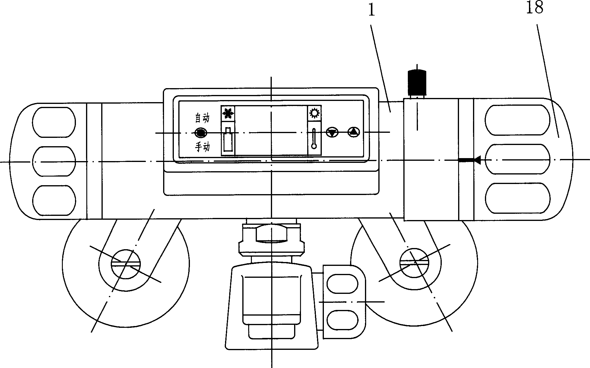
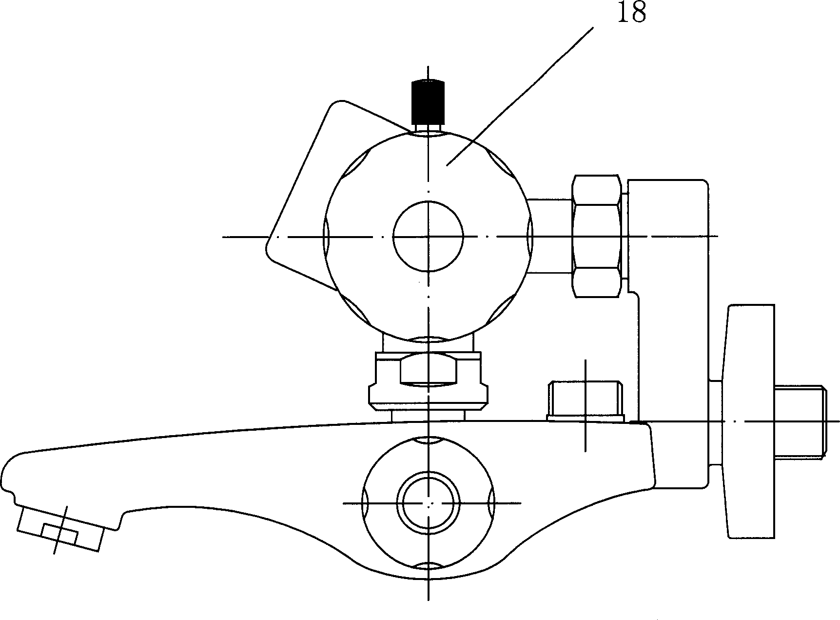
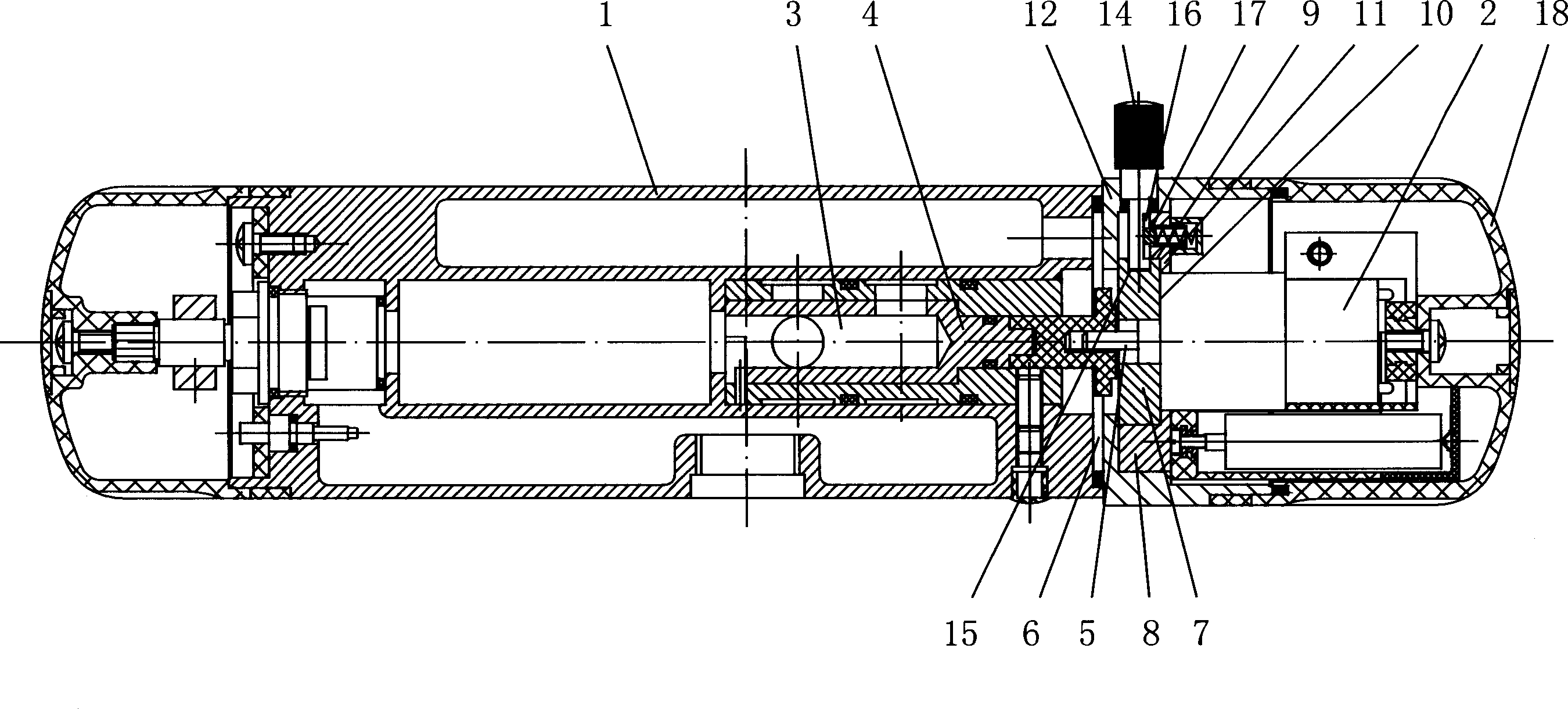
[0017] Example: such as figure 1 , figure 2 , image 3 , Figure 4 As shown, an electric and manual dual-purpose digital faucet includes a main body 1 and a reduction motor 2. The main body 1 is provided with a water mixing chamber 3, and the water mixing chamber 3 is provided with a spool 4. The spool 4 is connected to the reduction motor 1 Main shaft 5 is connected and fixed;

[0018] One end face 6 of the main body 1 is provided with a mounting seat 12, the main shaft 5 of the geared motor 2 passes through the mounting seat 12 and is connected to the valve core 4 and fixed, and a hand wheel 18 is fixed outside the geared motor 2, and the side wall of the hand wheel 18 and the mounting seat The side walls of 12 are joined, and the decelerating motor 2 is fixed with a positioning block 7 on the front end surface protruding from the main shaft 5. The positioning block 7 is provided with a pressing plate 8, and the pressing plate 8 is provided with a step hole 9. The positi...


PUM


Abstract

The electric and manual dual-purpose digital tap includes main body and speed-reducing motor, in the interior of main body a water-mixing cavity is set, in the water-mixing cavity a valve core is set, the valve cove is connected with main shaft of speed-reducing motor and fixed on it, the speed-reducing motor is fixed on main body, a locking mechanism is set between main body and speed-reducing motor. Said invention can adopt two modes of electric operation and manual operation to regulate water outlet temperature.

Description

technical field [0001] The invention relates to an electric and manual dual-purpose digital water tap. Background technique [0002] The State Intellectual Property Office announced on March 16, 2005 a utility model patent named "Numerical Control Thermostat Faucet", the patent number is ZL200420025754.4, which "discloses a CNC thermostat faucet, including a main body, a main body The water outlet chamber inside is equipped with a temperature sensor, a water outlet valve is provided between the temperature adjustment chamber and the water outlet chamber, and a tubular valve core is installed in the temperature adjustment chamber, one end of the valve core is connected to the motor through the valve stem, and the other end of the valve core There is an opening to communicate with the water outlet valve. There are hot water holes and cold water holes on the valve core. The axial positions of the water inlet hole, the hot water inlet hole and the cold water inlet hole are resp...

Claims


Application Information

Patent Timeline
IPC IPC(8): F16K11/085F16K31/05
Inventor 曹宇凡
Owner 曹宇凡
Learn More