Split structure for recycling cold water

A technology of cold water and diverter cavity, applied in the direction of valve operation/release device, valve details, multi-way valve, etc., can solve the problems of piston misjudgment, inability to start the diverter valve, affecting hot water supply, etc., and achieve the goal of improving accuracy Effect

Active Publication Date: 2017-11-10
重庆威贝琛电子有限公司
View PDF5 Cites 0 Cited by
  • Summary
  • Abstract
  • Description
  • Claims
  • Application Information

AI Technical Summary

Problems solved by technology

If things go on like this, it has not only caused a lot of waste of water resources, but also increased the additional expenses of users
[0003] At present, there are some technologies that can solve the above problems. For example, the temperature-adjusting cold and hot water diverter valve disclosed in Chinese Patent No. 201420249760.1 can solve the problem of cold water backflow, but it has the following problems: When there is water leakage or artificial leakage, the piston is prone to misjudgment and starts to work, which will waste hot water resources; and when the cold water circuit or the water inlet pipe is equipped with a water pump or a booster pump, it is easy to turn on the hot water faucet. There is a situation where the diverter valve cannot be activated, which will seriously affect the supply of hot water

Method used


Image

  • Split structure for recycling cold water
  • Split structure for recycling cold water
  • Split structure for recycling cold water

Examples


Embodiment 1

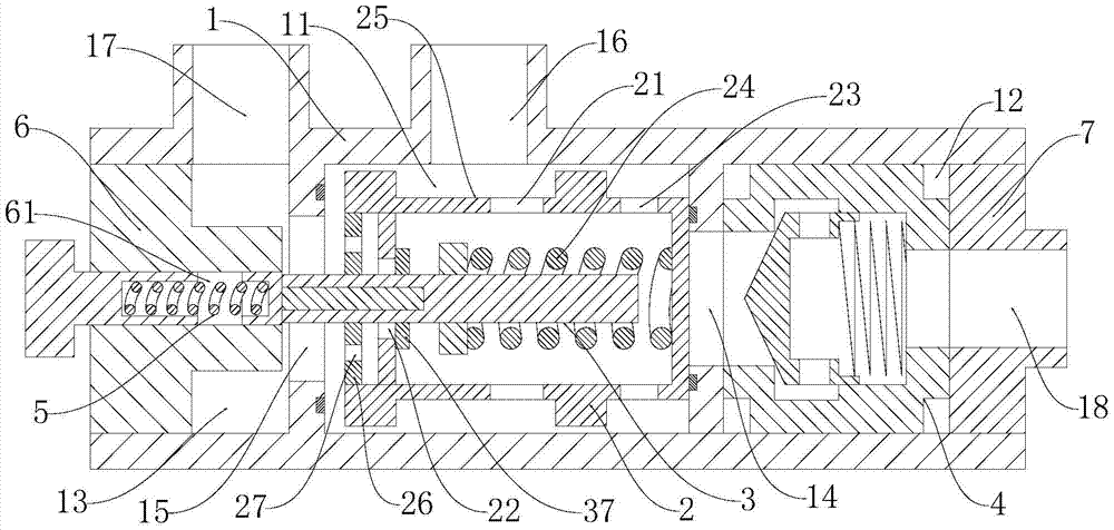
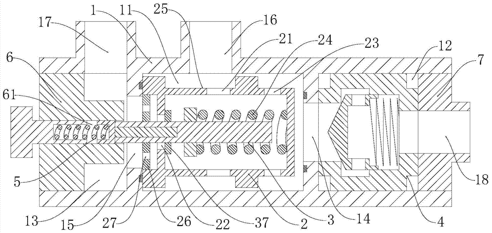
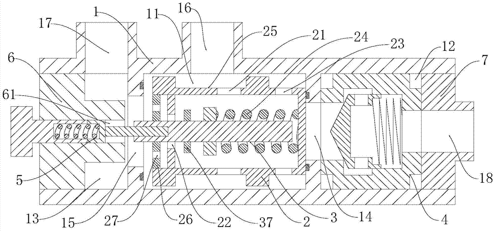
[0031] Such as Figure 1 to Figure 6 As shown, the shunt structure for recovering cold water includes an outer sleeve 1 with closed left and right ends and a hollow setting. The outer sleeve 1 is provided with a shunt chamber 11 and a return chamber 12 and a heat sink respectively located on both sides of the shunt chamber 11. The water chamber 13, the return chamber 12 communicates with the diversion chamber 11 through the first port 14, the hot water chamber 13 communicates with the diversion chamber 11 through the second port 15, and the return chamber 12 is provided with a single valve communicated with the first port 14. To the valve 4, a hollow piston barrel 2 is arranged in the distribution cavity 11, and there is a certain gap between the outer wall of the piston barrel 2 and the inner wall of the outer sleeve 1, and an annular groove 25 is arranged on the outer wall of the piston barrel 2, and the outer wall A water inlet 16, a hot water outlet 17 communicating with t...

Embodiment 2

[0036] This embodiment makes the following further limitations on the basis of Embodiment 1: the return chamber 12 is provided with a one-way valve 4 communicating with the first port 14, and the one-way valve 4 includes openings at both left and right ends. The valve body 41, the left end opening of the valve body 41 communicates with the first port 14, and the right end opening communicates with the return water outlet 18, and the valve body 41 is provided with a head 42 with the left end closing the right end opening and the second Three elastic parts 44, the width of the closed end of the head 42 is greater than the width of the opening at the left end of the valve body 41, the side wall of the head 42 is provided with a plurality of fourth through holes 43 communicating with the open end of the head 42, and the third elastic part 44 Act on the opening end of the sealing head 42 , so that the sealing head 42 closes the left end opening of the valve body 41 . When this embo...

Embodiment 3

[0038] This embodiment makes the following further limitations on the basis of any one of the embodiments 1-2: the left end cover 6 is provided with mounting holes 61 penetrating through the left and right end faces of the left end cover 6, and the elastic component 5 includes and installs The temperature regulating rod 51, the second elastic member 52 and the pressure sleeve 53 that are threaded in the hole 61, the temperature regulating rod 51 is placed in the end of the mounting hole 61 to be provided with an inner hole 54, and the inner hole 54 and the pressure sleeve 53 are respectively sleeved on the two ends of the second elastic member 52 . In this embodiment, in order to improve the stability of the interaction between the elastic component 5 and the temperature-sensitive actuator 3, the left end cover 6 should be provided with a sufficient thickness to ensure that the inner hole 54, the second elastic member 52 and the pressure sleeve 53 are all located in the install...


PUM


Abstract

The invention discloses a flow dividing structure used for recovering cold water. The flow dividing structure comprises an outer sleeve; a flow dividing cavity, a backflow cavity and a hot water cavity are arranged in the outer sleeve; the backflow cavity is communicated with the flow dividing cavity through a first port; the hot water cavity is communicated with the flow dividing cavity through a second port; a piston barrel is arranged in the flow dividing cavity; a certain gap exists between the outer wall of the piston barrel and the inner wall of the outer sleeve; a first through hole, a second through hole and a third through hole are formed in the barrel wall of the piston barrel; a temperature sensing actuator and a first elastic part are arranged in the piston barrel; the temperature sensing actuator is provided with a disk seal; the inner wall of the outer sleeve is provided with an elastic element; at least 1ML of water can be contained in the cavity located at the left side of the piston barrel in the outer sleeve. According to the flow dividing structure disclosed by the invention, accurate cold water and hot water flow dividing can be realized through sliding fit between the piston barrel and the outer sleeve, and meanwhile, the outlet water temperature of hot water can also be regulated as needed; the flow dividing structure has the advantages that judgment is accurate, the backflow efficiency is high, the operation is stable, and the service life is long.

Description

technical field [0001] The invention relates to the technical field of heating valves, in particular to a diversion structure for recycling cold water. Background technique [0002] In modern life, since the water supply pipe of the hot water supply system usually has a certain length, when hot water is used, a certain amount of retained cold water must be discharged every time to supply hot water, especially when the water point is far from the hot water supply point. This problem is particularly prominent at a distance. If things go on like this, it has both caused a large amount of waste of water resources and increased the additional expenses of users. [0003] At present, there are some technologies that can solve the above problems. For example, the temperature-adjusting cold and hot water diverter valve disclosed in Chinese Patent No. 201420249760.1 can solve the problem of cold water backflow, but it has the following problems: When water leaks or is caused by huma...

Claims


Application Information

Patent Timeline
Patent Type & Authority Patents(China)
IPC IPC(8): F16K11/044F16K31/64
CPCF16K11/044F16K31/002
Inventor 张良寅
Owner 重庆威贝琛电子有限公司
Why Eureka
Try Eureka