

Cylinder lock
A cylinder lock and cylinder technology, which is applied to cylinder marble locks, building locks, lock shells, etc., can solve the problems of difficult assembly of blocking parts and difficult assembly of blocking parts.
Inactive Publication Date: 2010-11-10
HUF HULSBECK & FURST GMBH & CO KG
View PDF8 Cites 0 Cited by
- Summary
- Abstract
- Description
- Claims
- Application Information
AI Technical Summary
Problems solved by technology
The disadvantage of this cylinder lock is that these protrusions make the blocking part difficult to assemble
In addition, in the known cylinder lock with anti-lost mechanism, if the safety mechanism is not installed in the interior of the cylinder core afterwards, then in the known cylinder lock with anti-lost mechanism, the The assembly of the plug is difficult
Method used
View moreImage
Smart ImageViewing Examples

Examples
Embodiment Construction
Login to View More PUM
 Abstract
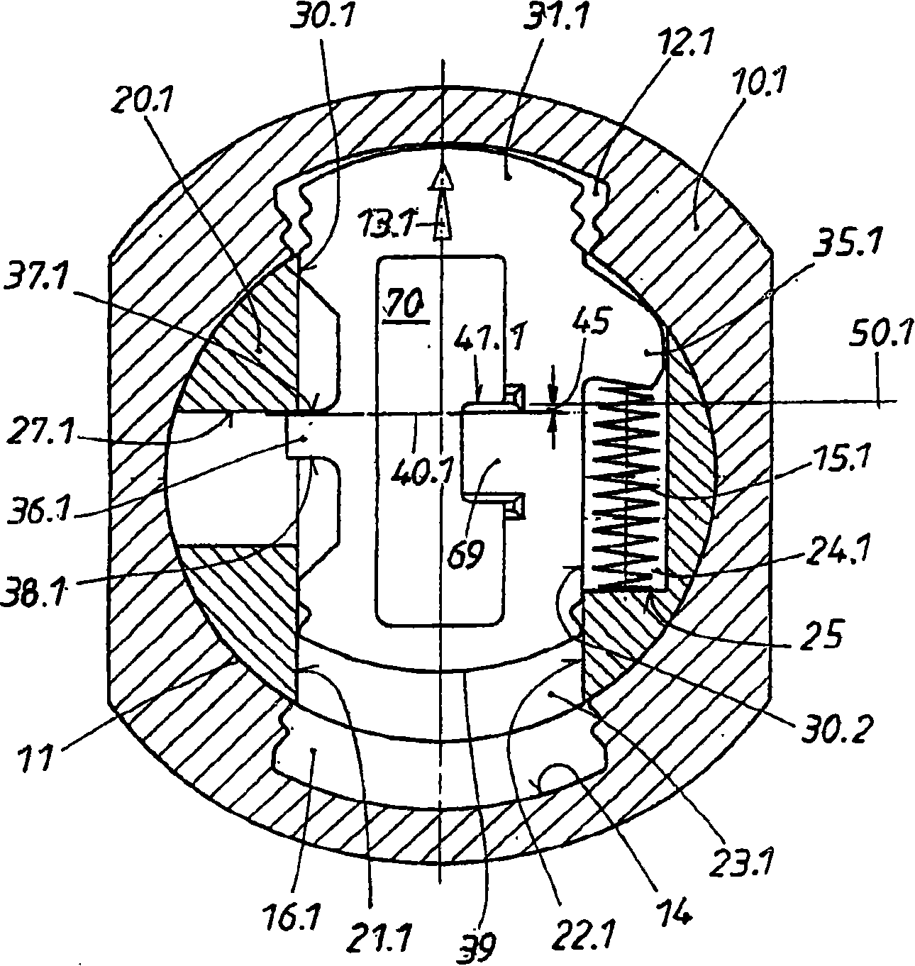
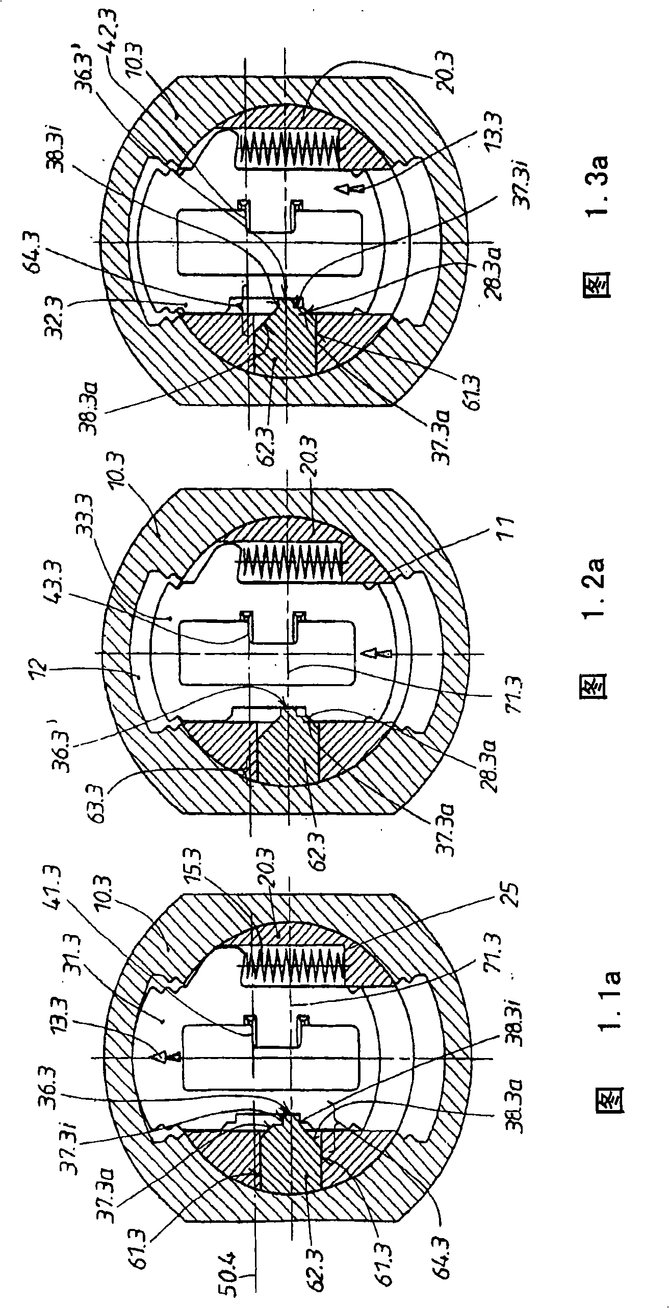
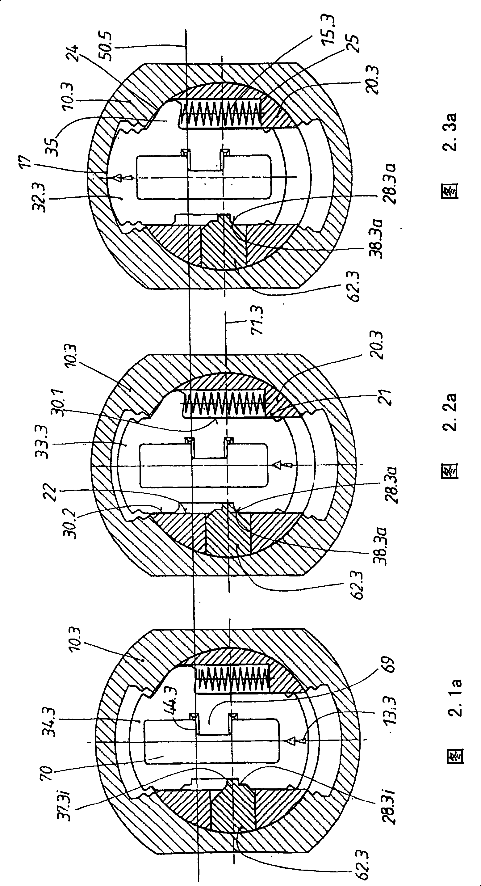
The cylinder lock is comprised of a cylinder housing (10.1) and of a cylinder core (20.1), which is mounted therein and which accommodates spring-loaded plate-shaped tumblers (31.1) that can be longitudinal placed therein. The plate longitudinal edges (30.1, 30.2) of the tumblers are then guided on guiding surfaces (21.1, 22.1) inside the cylinder core (20.1). The tumblers (31.1) have control edges (41.1) placed at defined heights (45). The aim of the invention is to render the cylinder lock not only burglar-proof, but to also ensure a reliable protection against the loss of tumblers. To thisend, the invention firstly provides that a cam (36.1) having a least one pair of flanks (37.1, 38.1) is placed either on one plate longitudinal edge (30.1) of the tumblers (31.1) or on the guiding surface in the cylinder core facing said plate longitudinal edge. The invention also provides that a cutout (26.1) is made either on the cylinder core (20.1) next to its cavity (23.1) for tumbler (31.1)or the cutout is made on the tumbler itself on its plate longitudinal edge facing the cam. Said cutout has at least one pair of mating flanks (27.1, 28.1) and is opposite the cam-side flanks (37.1, 38.1). The flanks and mating flanks (27.1, 37.1) function as a stop and counter sop for concealing the actual position of the control edges. At the same time, at least one flank and mating flank (27.1,37.1) provide for a protection against the loss of tumblers, which provides for a holding together of the modular unit, which consists of the spring-loaded (13.1) tumblers (31.1) and of the cylinder core (20.1), even when the modular unit is located outside of the cylinder housing (10.1).
Description
cylinder lock technical field The invention relates to a cylinder lock. The cylinder lock consists of a cylinder housing (Zylinder-gehaeuse) and a cylinder core (Zylinderkern) rotatably mounted therein. Cylinder locks are provided with a key having a defined longitudinal profile of the key which can be inserted into a cylinder core for turning operation. Arranged axially in the cylindrical core is a set of diametrical shafts in which plate-shaped closing elements are accommodated and can be moved longitudinally by means of their plate longitudinal edges. The blocking element is spring-loaded in one of its two directions of movement and has a control edge at a predetermined height which is designed according to the longitudinal contour of the key. In the rest position, ie when the key has been removed, the blocking element engages in a locking channel of the cylinder housing. When the key is inserted and removed, the blocking element can be temporarily deflected in a deflec...
Claims
Login to View More Application Information
Patent Timeline
 IPC IPC(8): E05B29/00
CPCE05B29/00E05B9/088Y10T70/7599
InventorG·巴伦伯格M·勒夫
OwnerHUF HULSBECK & FURST GMBH & CO KG