Automatic feeding device for pressure gauge assembler

A technology of automatic feeding and pressure gauge, applied in metal processing, metal processing equipment, manufacturing tools, etc., can solve problems such as trouble

Active Publication Date: 2019-01-08
安徽埃克森仪表有限公司
View PDF6 Cites 0 Cited by
  • Summary
  • Abstract
  • Description
  • Claims
  • Application Information

AI Technical Summary

Problems solved by technology

[0004] Although the existing pressure gauge tightening assembly machine has realized automatic tightening, it is semi-automatic and requires manual loading, which is very troublesome

Method used


Image

  • Automatic feeding device for pressure gauge assembler
  • Automatic feeding device for pressure gauge assembler
  • Automatic feeding device for pressure gauge assembler

Examples


Embodiment 1

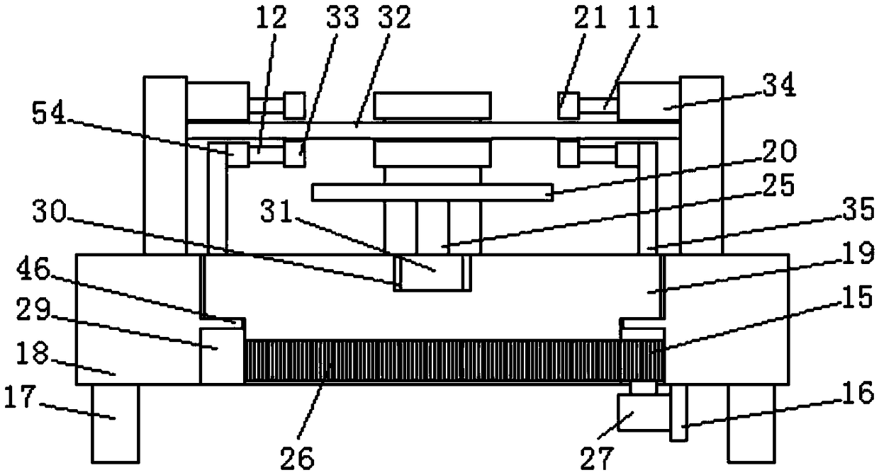
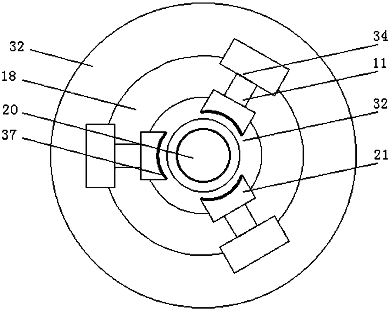
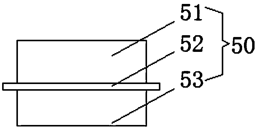
[0039] Embodiment 1, an automatic discharge device for a pressure gauge assembly machine, comprising a first conveyor belt 23, a fixed base 18, a pressure gauge 50 and a rotating base 19, the pressure gauge 50 is composed of a bottom cover 53, an upper cover 51 and a fixed The outer edge 52 is composed of the outer edge 52. The fixed outer edge 52 is arranged at the joint between the bottom cover 53 and the upper cover 51. The middle part of the fixed base 18 is provided with a rotation hole 29, and the inner wall of the middle part of the rotation hole 29 is provided with a fixing device for fixed connection. Ring 46, the fixed ring 46 is provided with a matching rotating base 19, the fixed base 18 is provided with a number of first fixed mounts 13 symmetrically distributed in the center, and the upper ends of the first fixed mounts 13 are provided with The first fixed bracket 13 is vertically fixedly connected to the first electro-hydraulic regulator 34, and the first electro...

Embodiment 2

[0048] The same as embodiment 1 is no longer repeated, and the difference with embodiment 1 is:

[0049] Further, the height of the fixing rod 24 on the side close to the conveying table 7 is higher than the height of the fixing rod 24 on the other side of the first conveying belt 23 . The second conveyor belt is set at a slant, so that the positioning frame can continuously rise when pushing the pressure gauge, so that the positioning frame can be separated from the pressure gauge effectively when the pressure gauge is pushed to the upper end of the conveying pipe, thus successfully for the next cycle.

Embodiment 3

[0051] The same as embodiment 1 is no longer repeated, and the difference with embodiment 1 is:

[0052] Preferably, the outer side of the upper end of the tray 20 is provided with a positioning groove 56 matching the size of the bottom cover 53 .

[0053] Further, a vertical connection delivery pipe 8 is provided between the delivery hole 55 and the support ring 32, the diameter of the delivery pipe 8 is larger than the inner diameter of the support ring 32, and the diameter of the delivery pipe 8 is smaller than the outer diameter of the support ring 32 , the two sides of one end of the positioning groove 56 are provided with symmetrically distributed adjusting grooves 43, the adjusting grooves 43 are provided with a connecting shaft 44 for movable connection, and the connecting shaft 44 is provided with a fixedly connected discharge rod 38, The inner wall of the support ring 32 is provided with a card slot 13 matching the discharge rod 38, the card slot 13 is arranged at th...


PUM


Abstract

The invention discloses an automatic feeding device for a pressure gauge assembler. The device comprises a first conveying belt, a fixed base, a pressure gauge and a rotating base; the pressure gaugeconsists of a bottom cover, an upper cover and a fixed outer edge; the fixed outer edge is arranged in the connecting place between the bottom cover and the upper cover; the rotating base is arrangedin the fixed base; a support ring is arranged at the upper end of the rotating base; a conveying table is arranged at the upper end of the support ring; the first conveying belt is arranged on one side of the conveying table; a second conveying belt is arranged at the upper end of the first conveying belt; the first conveying belt and the second conveying belt are connected through fixed rods; andthe fixed rod near one side of the conveying table is higher than the fixed rod on the other side of the first conveying belt. The device is simple in operation, high in comprehensive practicabilityand prone to popularization and application.

Description

Technical field: [0001] The invention relates to the technical field of pressure gauge assembly, in particular to an automatic feeding device for a pressure gauge assembly machine. Background technique: [0002] Pressure gauge (English name: pressure gauge) refers to an instrument that uses elastic elements as sensitive elements to measure and indicate pressure higher than the environment. It is widely used and it is used in almost all industrial processes and scientific research fields. It can be seen everywhere in heat pipe network, oil and gas transmission, water supply and gas supply system, vehicle repair and maintenance factory and shop. Especially in the process of industrial process control and technical measurement, due to the high mechanical strength and convenient production of the elastic sensitive components of mechanical pressure gauges, mechanical pressure gauges are more and more widely used. [0003] The pressure gauge casing is composed of a base and an up...

Claims


Application Information

Patent Timeline
Patent Type & Authority Applications(China)
IPC IPC(8): B23P19/00
Inventor 王汉元王炳华李贻华罗文君吴新林王万年杨云徐德洲
Owner 安徽埃克森仪表有限公司
Why Eureka
Try Eureka