Lamp tube current equalizing method and applied circuit

A lamp and circuit technology, applied in the field of lamp current equalization method and application circuit, can solve the problems of different inductance and inability to apply odd number of lamps, etc.

Inactive Publication Date: 2006-05-17
LIEN CHANG ELECTRONICS ENTERPRISE
View PDF0 Cites 0 Cited by
  • Summary
  • Abstract
  • Description
  • Claims
  • Application Information

AI Technical Summary

Problems solved by technology

[0009] The existing circuit for adjusting the lamp current in the above description has a common disadvantage, that is, when the circuit is applied to multiple lamps, it can only be applied to the balance between two lamps, and cannot be applied to an odd number of lamps on, and with Image 6 For example, the inductance of the coils at each level is different and can only be applied to the number of lamp tubes to the power of two

Method used


Image

  • Lamp tube current equalizing method and applied circuit
  • Lamp tube current equalizing method and applied circuit
  • Lamp tube current equalizing method and applied circuit

Examples


Embodiment Construction

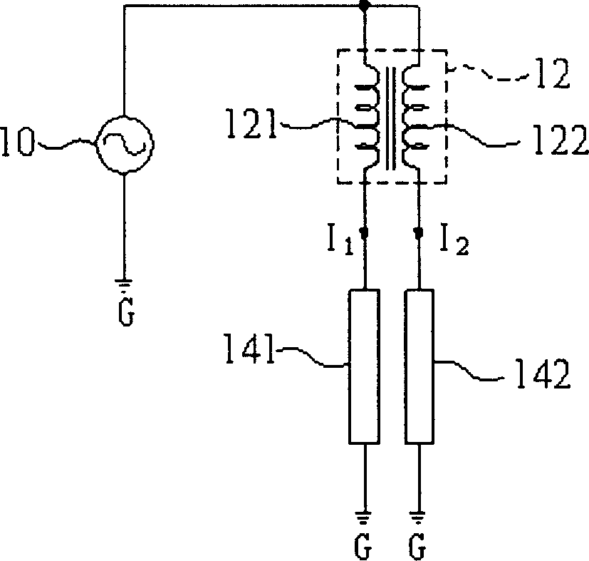
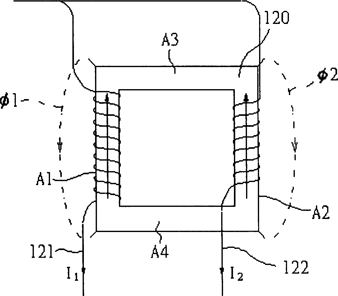
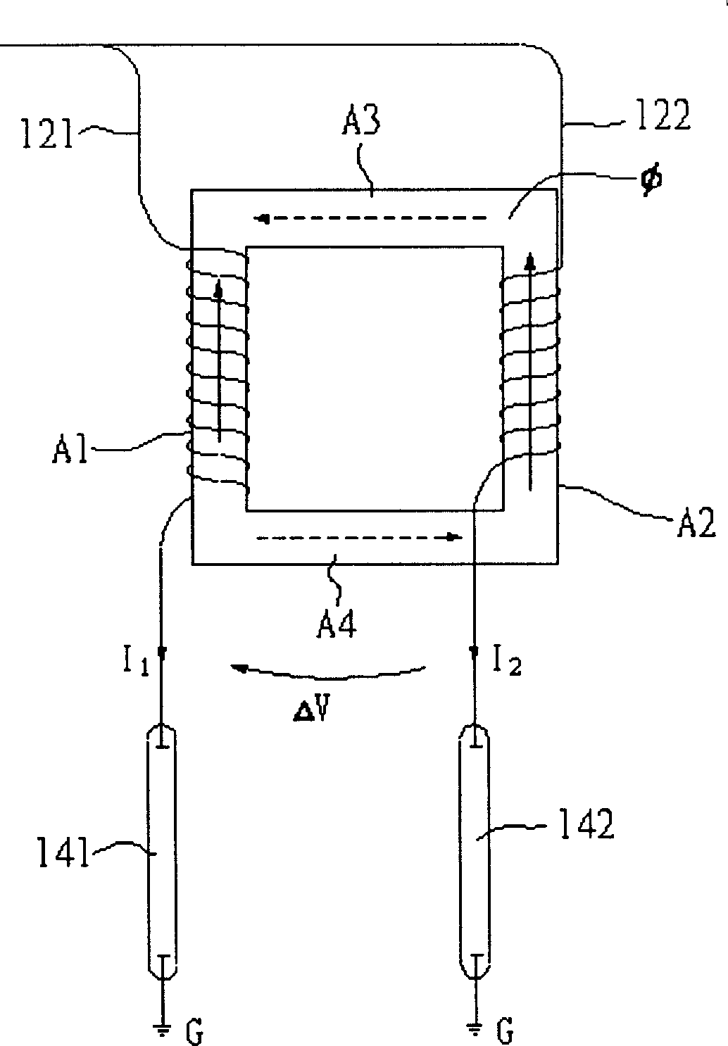
[0046] Please refer to Figure 7 , is a schematic diagram of current equalization and application of two lamp tubes of the present invention. Figure 7 The circuit shown takes two light tubes as an example, which includes two light tubes L1, L2, and one end of the two light tubes L1, L2 is respectively connected to a power source V sec , and the other ends are respectively connected to one side winding L1 of the transformers T1 and T2 P , L2 P , the other side winding L1 of the transformer T1, T2 S , L2 S It is connected in series to form a closed loop. Due to the electromagnetic induction characteristics of transformers T1 and T2, and through the winding L1 on one side of these transformers T1 and T2 S , L2 S The closed loop formed by series connection makes it flow through one side of the winding L1 S , L2 S The current ix is ​​equal, thus, the power source V sec provide the same operating current i 1 i 2 To the two lamps L1, L2. In the above description, the tra...


PUM


Abstract

A method for providing equalized current on lamp tube includes connecting one side winding of multiple transformers to multiple lamp tubes, connecting another side winding in series to form a closed loop, making current flowing on one side winding be equal to let lamp tube connected on another side winding generate the same operation current by utilizing magnetic ¿C inductive property of transformer and closed loop formed on one side winding of transformer.

Description

technical field [0001] The invention relates to a lamp current equalization method and an application circuit, in particular to a lamp current equalization method and an application circuit for adjusting the current balance between multiple lamp tubes by utilizing the connection relationship between multiple transformers and multiple lamp tubes . Background technique [0002] Due to technological progress and consumer demand, the size of LCD panels continues to increase, so that a single light tube can no longer meet its lighting requirements, so two or more light tubes need to be used. In order to ensure uniform brightness of the LCD panel, the current of each lamp tube must be adjusted at any time so that the current flowing through each lamp tube is equal. However, due to various reasons such as high instability and negative impedance characteristics of the cold cathode fluorescent lamp (CCFL), it is difficult to maintain the same impedance of the lamp tubes, resulting i...

Claims


Application Information

Patent Timeline
Patent Type & Authority Applications(China)
IPC IPC(8): H05B41/295H05B41/14
Inventor 陈振刚王政雄
Owner LIEN CHANG ELECTRONICS ENTERPRISE
Why Eureka
Try Eureka