Electronic timepiece

A technology for electronic clocks and operating devices, which is applied to electromechanical clocks, clocks, and electrical means to indicate time, etc., and can solve problems such as the problem of switch durability.

Inactive Publication Date: 2006-06-07
SEIKO INSTR INC
View PDF0 Cites 3 Cited by
  • Summary
  • Abstract
  • Description
  • Claims
  • Application Information

AI Technical Summary

Problems solved by technology

Therefore, even when the time correction is not performed, the switch comes into conta

Method used


Image

  • Electronic timepiece
  • Electronic timepiece
  • Electronic timepiece

Examples


Embodiment Construction

[0019] An electronic clock according to an embodiment of the present invention will be explained below.

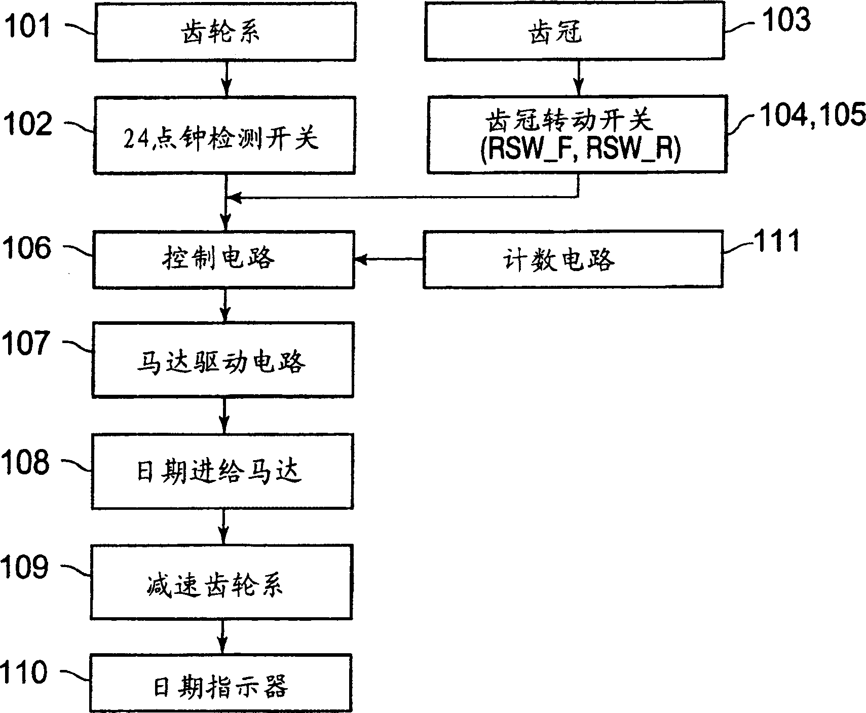
[0020] attached figure 1 is a block diagram of an electronic clock according to an embodiment of the present invention. The electronic clock according to the embodiment is an example of a so-called 2-motor type electronic clock, which has a motor for driving to rotate one time hand (hour hand, minute hand or second hand) and a motor for driving to rotate a date display device. motor.

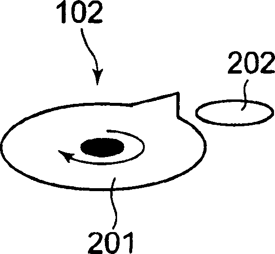
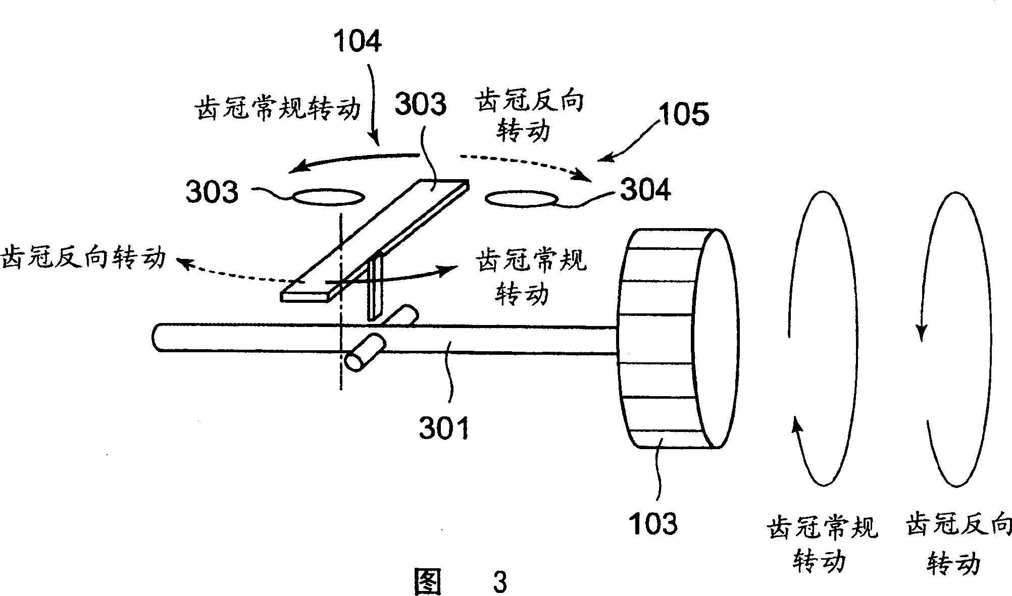
[0021] in the attached figure 1 Among them, the electronic clock includes a gear train 101, which is a mechanical structure used to drive the time hand to rotate, a 24 o'clock detection switch 102 used to detect 24 o'clock, a crown 103 as an operating device, and a first and second switch. Two crown rotation switches 104, 105 for detecting the rotation direction of the crown 103, a control circuit 106 for controlling each component and the entire electronic clock, for driving a rotation m...


PUM


Abstract

In order to provide an electronic clock with a simple structure and excellent durability and to change the date display of the date display device according to the rotation of the time hand, the 24 o'clock detection switch detects 24 o'clock, when the tooth crown used to rotate the time hand The crown rotation switch is set ON when the crown rotation switch is normally rotated by a predetermined angle and is set ON when the crown rotation switch is reversely rotated by a predetermined angle, and the control circuit operates based on the number of operations for which the crown rotation switch is set ON. Determine whether the rotation direction of the tooth crown is normal rotation or reverse rotation. When the 24 o'clock detection switch detects 24 o'clock, the control circuit 106 will perform normal rotation or reverse rotation in the direction consistent with the determination result of the rotation direction of the tooth crown. Turn the date display of the date display device to change the date to tomorrow or yesterday.

Description

technical field [0001] The invention relates to an electronic clock, which is used to change the date display of the date display device according to the rotation of the time hand. Background technique [0002] In the background technology, the date display function is provided as an additional function of the clock, and the function of displaying the date is used to determine whether the execution of the date feeding device in the forward direction of the date (tomorrow) or the backward direction of the date (yesterday) is consistent with the movement of the clock hands Consistent (regular or reverse feed for date determination) (Refers to e.g. patent ref 1, patent ref 2). [0003] According to the electronic clock described in the aforementioned patent reference 1, two switches are used to determine the normal or reverse direction of rotation of the date. Both switches are always in contact with the plate, even in normal manual operation (no time correction at this time),...

Claims


Application Information

Patent Timeline
IPC IPC(8): G04B19/24G04B19/02G04C3/00
CPCG04C3/007G04C9/08G04C17/0066
Inventor 井桥朋宽
Owner SEIKO INSTR INC
Why Eureka
Try Eureka