Trigger Switch Mechanism of Nail Gun

a switch mechanism and nail gun technology, applied in the direction of woodworking apparatus, manufacturing tools, portable drilling machines, etc., can solve the problems of inability to conveniently switch the switch mechanism in the trigger by both hands, the block piece in the trigger cannot be induced to move, and the trigger valve cannot be actuated, so as to achieve convenient switching

Inactive Publication Date: 2008-08-07
DE POAN PENUMATIC
View PDF20 Cites 23 Cited by
  • Summary
  • Abstract
  • Description
  • Claims
  • Application Information

AI Technical Summary

Benefits of technology

[0009]A trigger switch mechanism for a nail gun is capable of conveniently switching the operation modes of one of the sequential actu

Problems solved by technology

If the operator disobeys the operating sequence, i.e. pressing the trigger firstly, and then pressing the safety slide rod or the hitting base, the blocking piece in the trigger cannot be induced to move with and the trigger valve cannot be actuated.
However, during the process of operating the nail gun, the operator has to grasp the workpiece or tools by another hand.
In other wo

Method used


Image

  • Trigger Switch Mechanism of Nail Gun
  • Trigger Switch Mechanism of Nail Gun
  • Trigger Switch Mechanism of Nail Gun

Examples


first embodiment

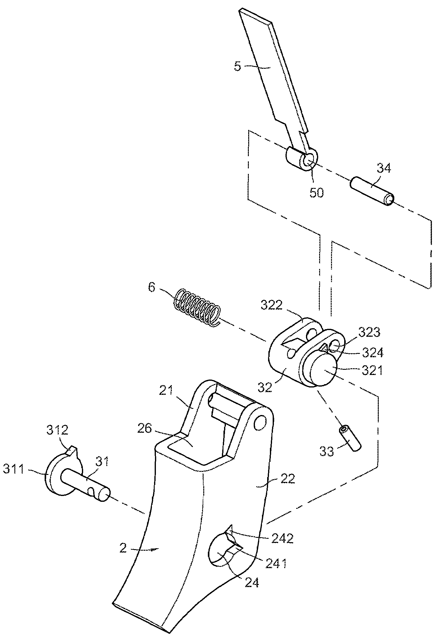
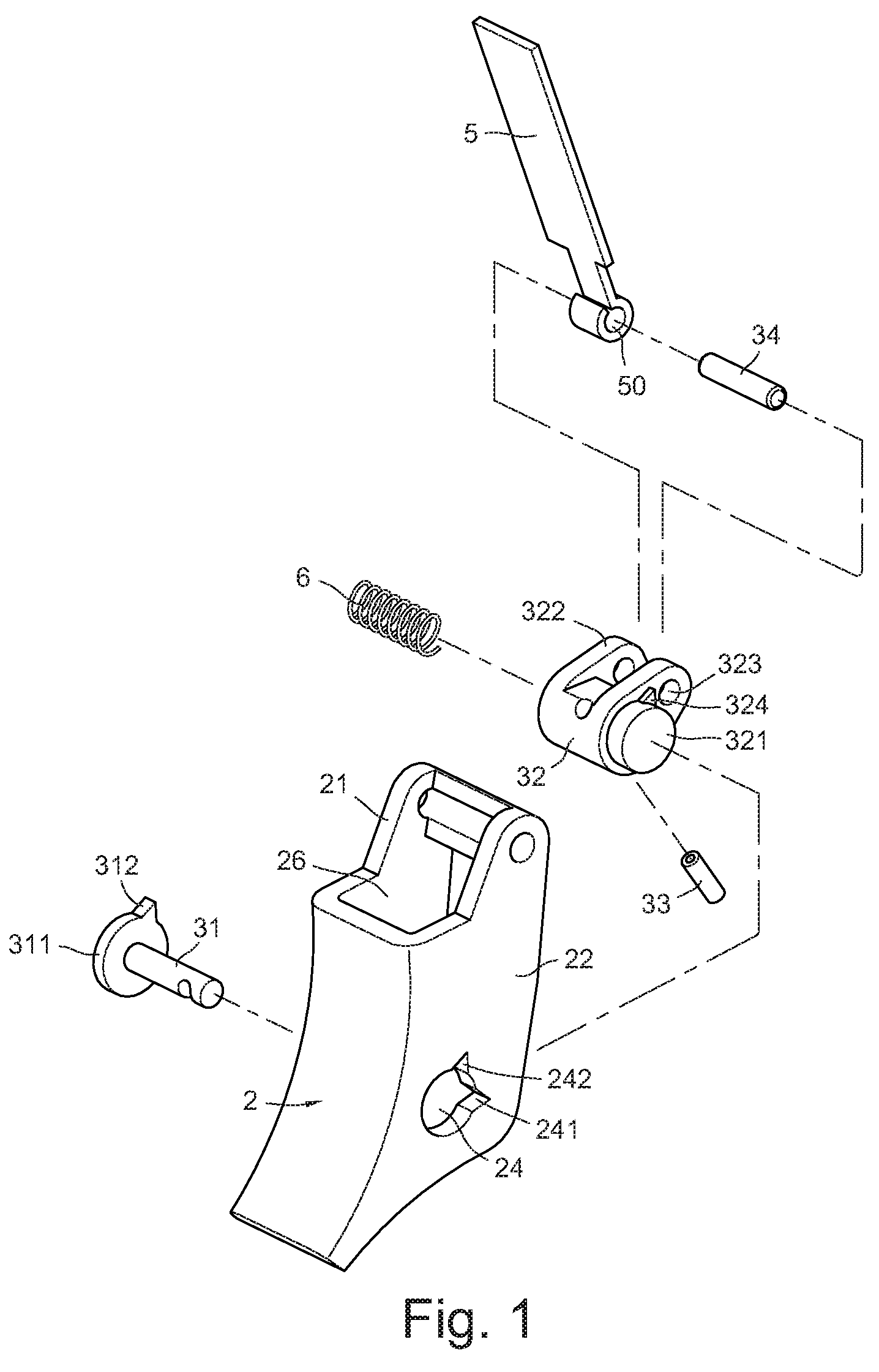
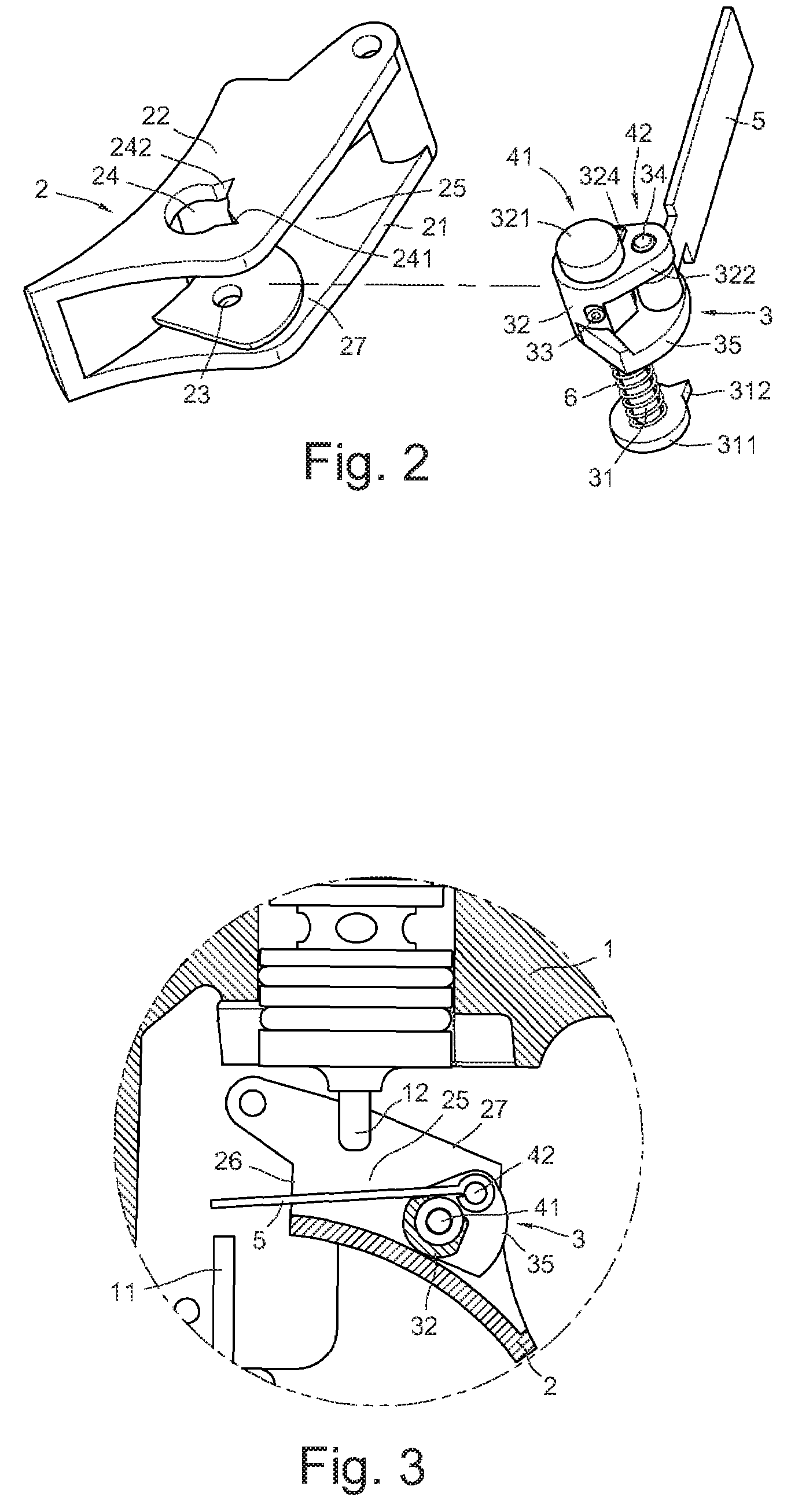
[0035]Referring to FIG. 1, an exploded, perspective view of a trigger switch mechanism according to the present invention is shown. Also referring to FIGS. 2, 3 and 4, a trigger 2 is pivotally attached between a safety slide rod 11 and a trigger valve rod 12 of a nail gun 1. The cross-sectional view of the trigger 2 has a U-shaped, and the trigger 2 includes two side plates 21 and 22, a receiving groove 25 formed between the two side plates 21 and 22 having an opening 26 and a notch 27. Each of the side plates 21 and 22 includes an axis hole 23 and 24 (as shown in FIGS. 5 and 5a), and a switch mechanism 3 is pivotally attached between the two axis holes 23 and 24.

[0036]The switch mechanism 3 includes a fixing bolt 33 prong into a base portion 32 for locating an axis rod 31, and the axis rod 31 is integrated with the base portion 32 (as shown in FIGS. 6, 6a, and 6b). The base portion 32 and the axis rod 31 cooperatively form a first continuous pivot portion 41 (as shown in FIGS. 2 an...

second embodiment

[0050]Referring to FIG. 16, a perspective view of a trigger switch mechanism according to the present invention is shown. The axis hole 23 of the side plate 21 includes a guiding groove 233 (as shown in FIG. 16), and the axis hole 24 of the side plate 22 includes two blocking grooves 241 and 242 (as shown in FIG. 5a). The first blocking teeth 312 of the switch mechanism 3 slidably disposed in the guiding groove 233, and the second blocking teeth 324 of the switch mechanism 3 nested in the blocking grooves 241 and 242. Variously, the axis hole 23 of the side plate 21 includes two blocking grooves 231 and 232, and a guiding groove 233 (as shown in FIG. 5), and the first blocking teeth 312 of the switch mechanism 3a slidably disposed in the guiding grooves 233 and nested into the blocking grooves 231 and 232. And the axis hole 24 of the side plate 22 has no blocking grooves (as shown in FIG. 17). Meanwhile, the second pivot axis 321 of the switch mechanism 3a has no blocking teeth (as ...


PUM

PropertyMeasurementUnit
Timeaaaaaaaaaa

Abstract

A trigger switch mechanism of a nail gun is pivotally attached between two side plates of a trigger of the nail gun. The switch mechanism includes a blocking piece pivotally attached to a safety slide rod and a trigger valve rod of the nail gun. Each of the side plates includes an axis hole, and two blocking grooves are disposed in the axis hole. The switch mechanism includes a plurality of blocking teeth, and a spring is disposed between one of the side plate and the switch mechanism to abut the switch mechanism and nest the blocking teeth into the blocking groove for stopping the switch mechanism. The switch mechanism includes a dial portion for being dialed by a hand of the operator, which is capable of deviating the blocking teeth from the blocking grooves to release the switch mechanism, and rotating the switch mechanism to adjust the position of the blocking piece relative to the safety slide rod, so as to realize conveniently switching the operation modes of the trigger of the nail gun.

Description

BACKGROUND[0001]The present invention relates to trigger switch mechanisms of pneumatic nail guns, and more particularly to a switch mechanism pivotally attached in a trigger of a nail gun, for switching the nail gun to operate in one of a sequential actuation mode and a contact actuation mode.[0002]Pneumatic nail gun generally utilizes a compressed high pressure air in an air chamber thereof to drive a hitting rod to hit a nail, for join two objects by activating a nail through both objects, which are widely used in woodworking. The operation of the hitting rod is jointly controlled by a trigger and a safety slide rod of the nail gun.[0003]Actuating nails of a nail gun generally can be divided into two types: sequential actuation mode and contact actuation mode.[0004]For sequential actuation mode, before driving the nails, the operator should press a safety slide rod or a hitting base on the safety slide rod contacting on a surface of a workpiece to push a blocking piece in a trigg...

Claims


Application Information

Patent Timeline
IPC IPC(8): B25C1/00
CPCB25C1/04
Inventor HUANG, CHI-SHENG
Owner DE POAN PENUMATIC
Why Eureka
Try Eureka