

Intelligent capacitive swipe switch
- Summary
- Abstract
- Description
- Claims
- Application Information
AI Technical Summary
Benefits of technology
Problems solved by technology
Method used
Image

Examples
Embodiment Construction
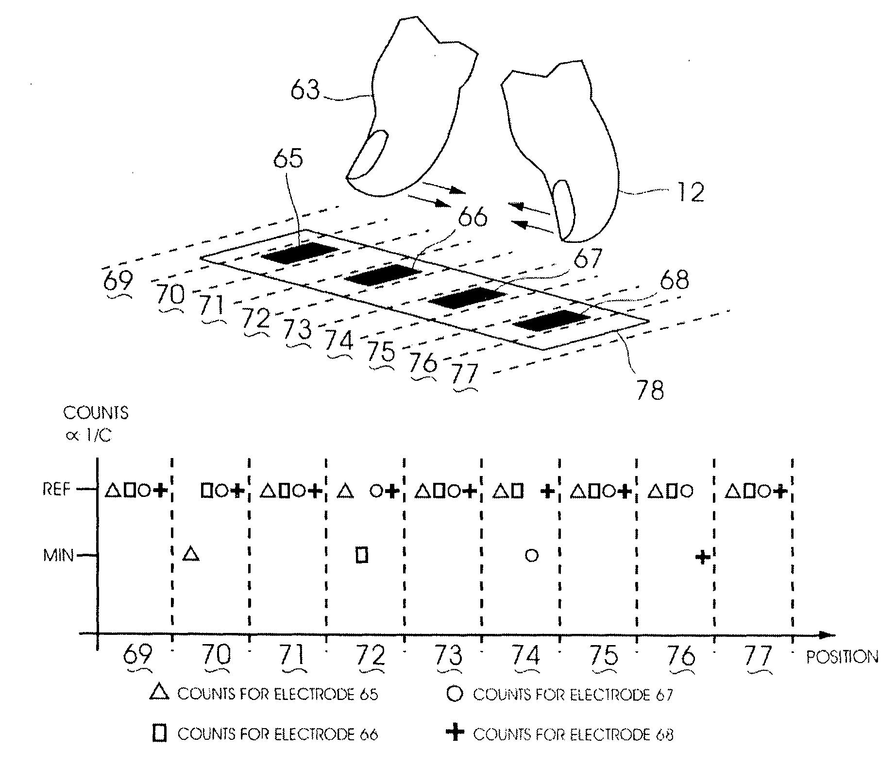
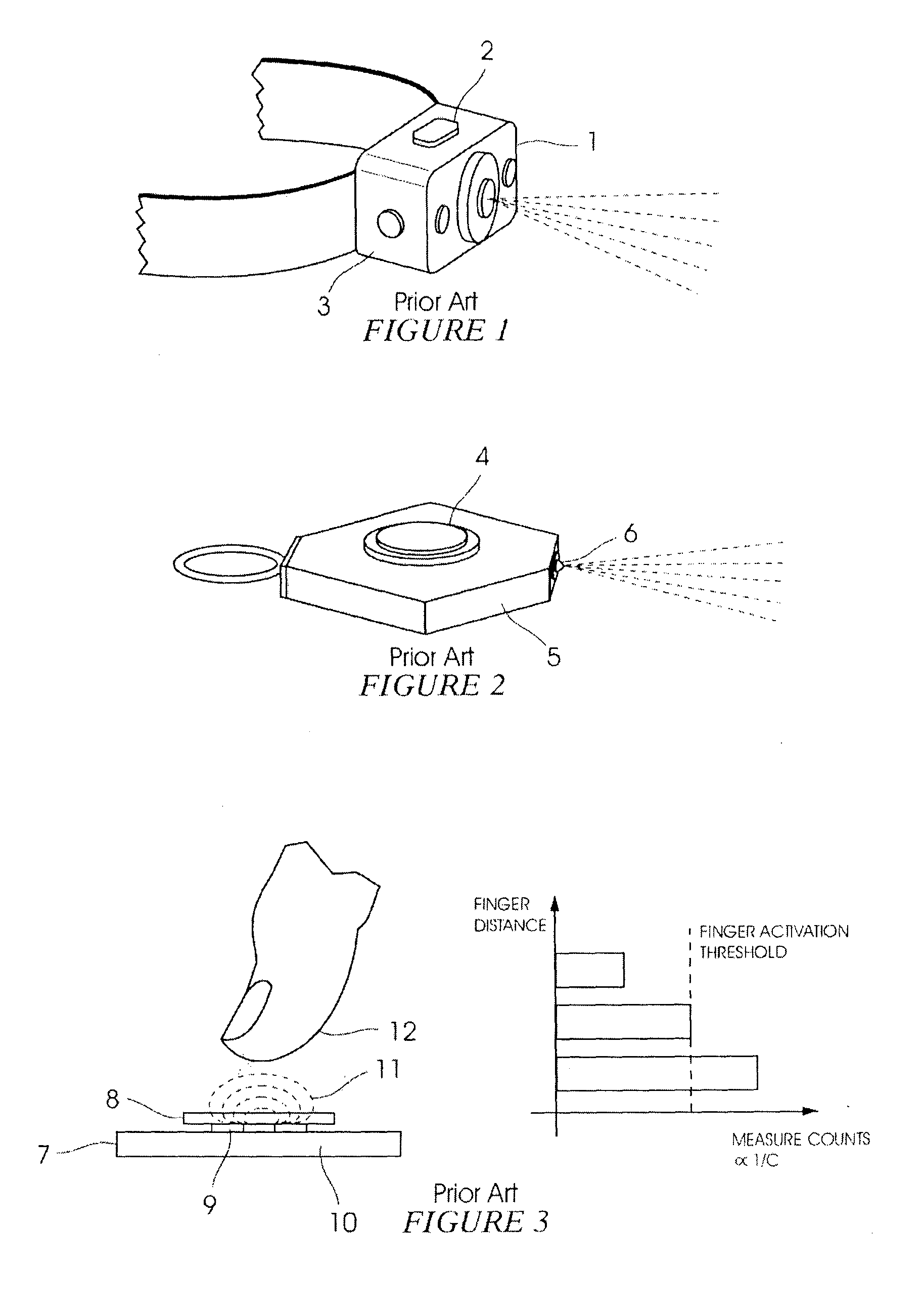
[0081]FIGS. 1 and 2 show a typical headlamp (1) and key-ring switch (5) according to the prior art. As mentioned above, these may typically employ mechanical switches (2) and (4) to facilitate user interfaces, with the stated drawbacks and challenges. It should be noted that prior art mechanical switches may also be prone to inadvertent activations, for instance when the unit is carried in user's trouser pocket, or in a backpack.
[0082]FIG. 3 illustrate a typical capacitive switch of the prior art, in this case using projected, or mutual capacitance measurements. If electrode (9) is a transmitter, and electrode (10) is a receiver electrode, both covered by dielectric material (8) and supported by substrate (7), electric field patterns may typically be as illustrated by (11). As the user finger (12) approaches the electrode pair, it should perturb the electric field patterns, resulting in reduced coupling and measured capacitance. This is illustrated by the bar graph of FIG. 3. When u...
PUM
 Abstract
Description
Claims
Application Information