Illumination-type rotational control device

a control device and rotating control technology, applied in the direction of mechanical control devices, controlling members, instruments, etc., can solve the problems of increasing the amount of light wasted, insufficient brightness of indicators, increasing the amount of electric power consumed by light sources, etc., to effectively use light emerging, illuminate the pointer display element, and lengthen the direction parallel

Inactive Publication Date: 2007-08-23
ALPS ALPINE CO LTD
View PDF13 Cites 24 Cited by
  • Summary
  • Abstract
  • Description
  • Claims
  • Application Information

AI Technical Summary

Benefits of technology

[0010]In the illumination-type rotational control device configured as described above, the light guiding unit is integral with the rotatable control knob has the illuminating portion disposed in the pointer display element, where the strip light-guiding portion annularly extends along the inner surface of the control knob. Therefore, most of light emerging from the planar light-emitting unit and incident on the lower surface of the strip light-guiding portion can be guided to the illuminating portion without being wasted. Thus, it is made possible to illuminate the pointer display element for an indicator at high intensity, by effectively using light emerging from the planar light-emitting unit.
[0011]In the above-described configuration of the light guiding unit, the length in the direction parallel to the rotational axis of the control knob may be constant, from the illuminating portion at one end to the other end. However, it is preferable that the length in the direction parallel to the rotational axis of the control knob decreases with distance from the illuminating portion. In other words, it is preferable that the shape of the strip light-guiding portion be triangular with the illuminating portion as the base. With the strip light-guiding portion having such a configuration, light emerging from the planar light-emitting unit and incident on the lower surface of the strip light-guiding portion can be more easily reflected off the upper surface as feedback light. Therefore, light emerging from the planar light-emitting unit can be effectively guided through the strip light-guiding portion to the illuminating portion. It will be sufficient if either of the upper and lower surfaces of the strip light-guiding portion includes an inclined surface. However, light from the planar light-emitting unit can be more effectively guided to the illuminating portion if both the upper and lower surfaces of the strip light-guiding portion are inclined wit respect to respective planes orthogonal to the rotational axis of the control knob.
[0012]In the configuration described above, it will be sufficient if the planar light-emitting unit has a planar light exiting surface, which allows light to be incident on the lower surface of the strip light-guiding portion. However, it is further preferable if the planar light-emitting unit has an annular light exiting surface which allows light emitted from a light source to emerge obliquely toward the lower surface of the strip light-guiding portion, because the light emerging from the planar light-emitting unit can be incident on the light receiving surface of the strip light-guiding portion without being wasted.
[0013]In the illumination-type rotational control device of the present invention, the light guiding unit is integral with the rotatable control knob and has the illuminating portion disposed in the pointer display element with the strip light-guiding portion annularly extending along the inner surface of the control knob. The illumination-type rotational control device is configured such that light emerging from the planar light-emitting unit is incident on the lower surface of the strip light-guiding portion and is guided to the illuminating portion. Therefore, most of light emerging from the planar light-emitting unit and incident on the lower surface of the strip light-guiding portion can be guided to the illuminating portion without being wasted. Thus, it is made possible to illuminate the pointer display element for an indicator at high intensity, by effectively using light emerging from the planar light-emitting unit.

Problems solved by technology

This increases the amount of light wasted because it is blocked by the backside of the control knob and cannot be used as light for illuminating the indicator.
Also, this causes problems of insufficient brightness of the indicator and an increase in the amount of electric power consumed by the light source.

Method used


Image

  • Illumination-type rotational control device
  • Illumination-type rotational control device
  • Illumination-type rotational control device

Examples


Embodiment Construction

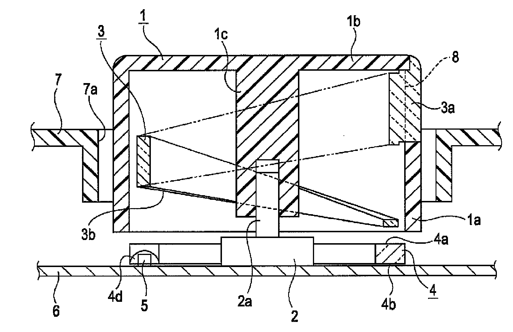
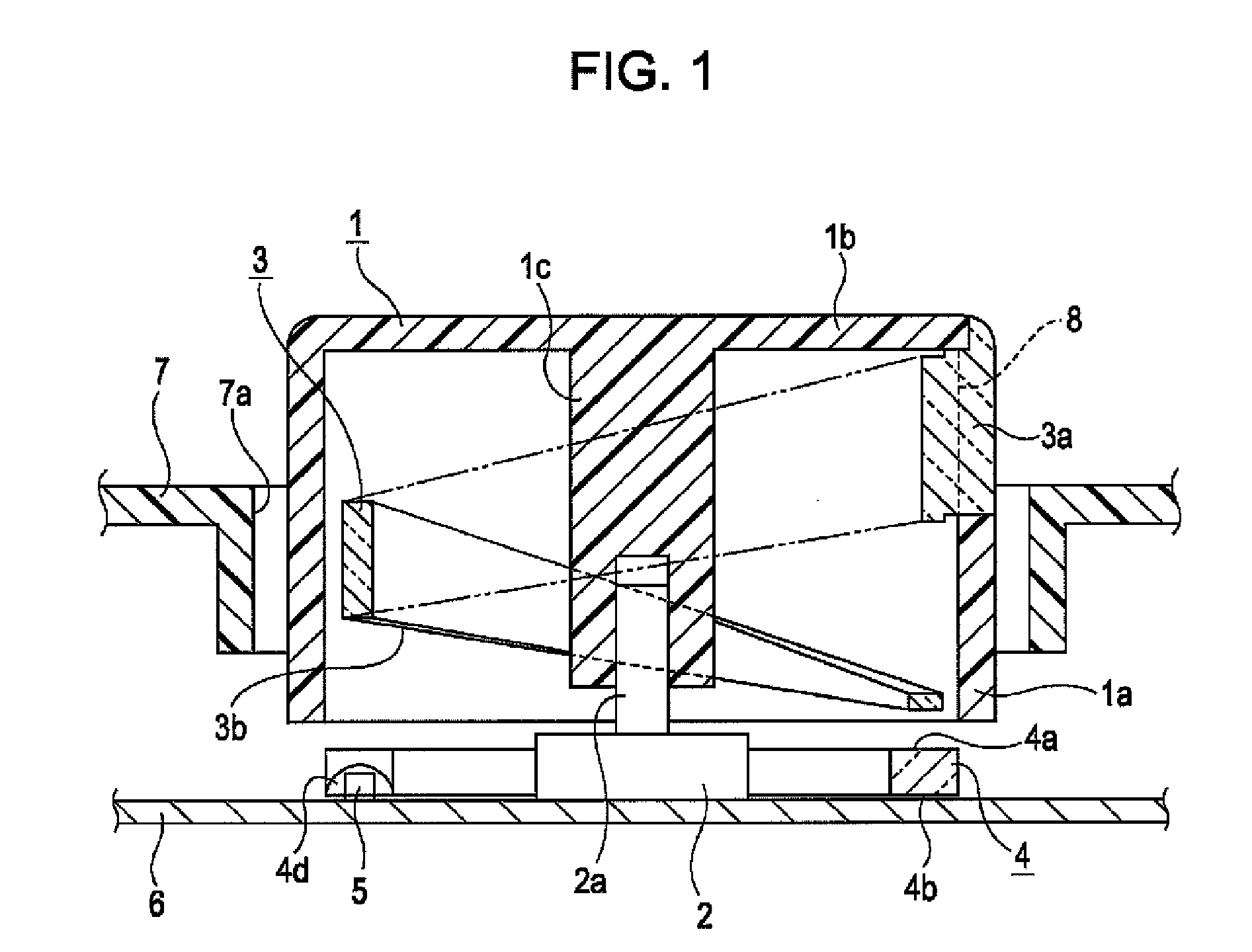
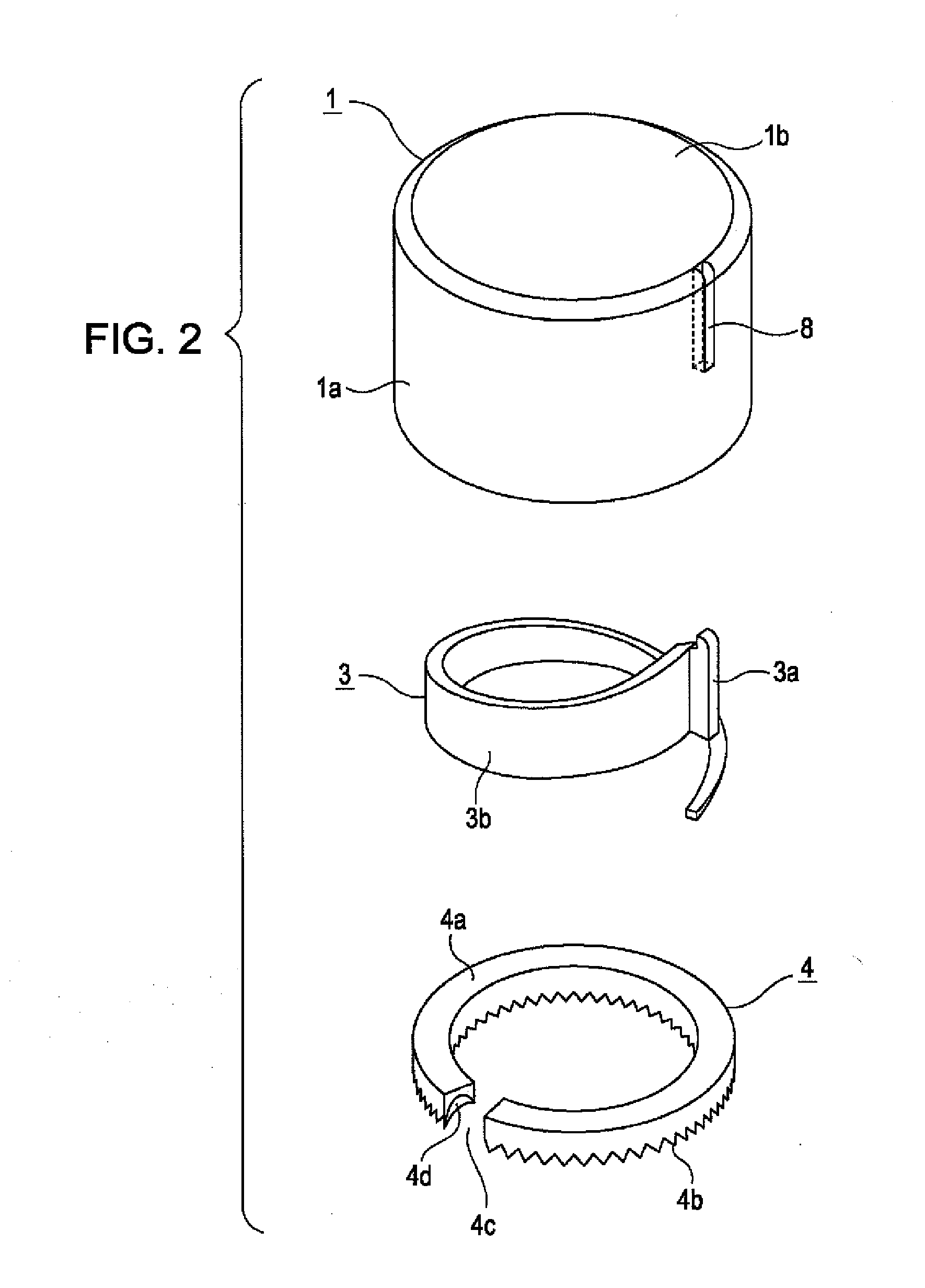
[0019]Embodiments of the present invention will now be described in detail with reference to the drawings. FIG. 1 is a cross-sectional view of an illumination-type rotational control device according to an embodiment of the present invention. FIG. 2 is an exploded perspective view of main parts of the illumination-type rotational control device. FIG. 3 is a perspective view of a light guiding unit in the illumination-type rotational control device, and illustrates the light guiding unit in an orientation different from that in FIG. 2. FIG. 4 is a plan view of the light guiding unit. FIG. 5 illustrates paths of light emerging from a planar light-emitting unit and incident on the light guiding unit.

[0020]An illumination-type rotational control device of the present invention is mounted on a vehicle instrument panel, center console box, and the like, and is used, for example, as an input means for setting a temperature of an air conditioning system. As illustrated in FIG. 1, the illumi...


PUM


Abstract

A rotatable control knob for actuating a rotary switch includes a slit serving as a pointer display element. An illuminating portion of a light guiding unit attached to the control knob is disposed in the slit. A strip light-guiding portion extends spirally from the illuminating portion is secured to the inner surface of the control knob. Thus, light emerging from a planar light-emitting unit disposed under the control knob is incident on the lower surface of the strip light-guiding portion and is guided through the strip light-guiding portion to the illuminating portion. This allows the illuminating portion illuminated with high intensity in the slit so as to function as an indicator.

Description

[0001]This application claims the benefit of priority under 35 U.S.C. §119 to Japanese Patent Application No. 2006-041079, filed Feb. 17, 2006, which is hereby incorporated by reference in its entirety.BACKGROUND OF THE INVENTION[0002]1. Field of the Invention[0003]The present invention relates to illumination-type rotational control devices mounted on vehicle instrument panels and the like, which are used as a variety of input means, and particularly relates to an illuminating mechanism for an indicator provided in a rotatable control knob.[0004]2. Description of the Related Art[0005]For a rotational control device included in in-vehicle air conditioning systems, audio systems, and the like, it is necessary that a rotational position of a control knob to be manually operated by an operator (i.e., driver or passenger) is visible, even in a poorly lit environment. Therefore, an illuminating mechanism for illuminating a pointer display element of a control knob with light from the bac...

Claims


Application Information

Patent Timeline
Patent Type & Authority Applications(United States)
IPC IPC(8): G01D11/28
CPCG01D11/28G05G1/105
Inventor NISHIYAMA, YOSHINOARIKOBAYASHI, AYUMU
Owner ALPS ALPINE CO LTD
Why Eureka
Try Eureka