Light base structure of high-power LED street lamp

Inactive Publication Date: 2009-10-22
GENIUS ELECTRONICS OPTICAL CO LTD
View PDF21 Cites 108 Cited by
  • Summary
  • Abstract
  • Description
  • Claims
  • Application Information

AI Technical Summary

Benefits of technology

[0003]The purpose of this invention is to propose a light base structure for containing high-power LED modules and produce optimal optical effects, including broaden lighted range and enhancing brightness and uniformity in effective lighted area.
[0004]To reach the end, the invention proposes a light base structure of a high-power LED street lamp that contains: a concaved room (polygon-shaped in its sectional view) in one side of the base. Taking a central line for the concaved room, both sides apart from the central

Problems solved by technology

Although such structure makes lighted range bigger, its actual performance on lighting effects is still controversial This is because the included angle of the two outermost mounting faces is around 120 degrees, and also the included angles of adjacent pair of mounting faces are big.
That would probably cau

Method used


Image

  • Light base structure of high-power LED street lamp
  • Light base structure of high-power LED street lamp
  • Light base structure of high-power LED street lamp

Examples


Example

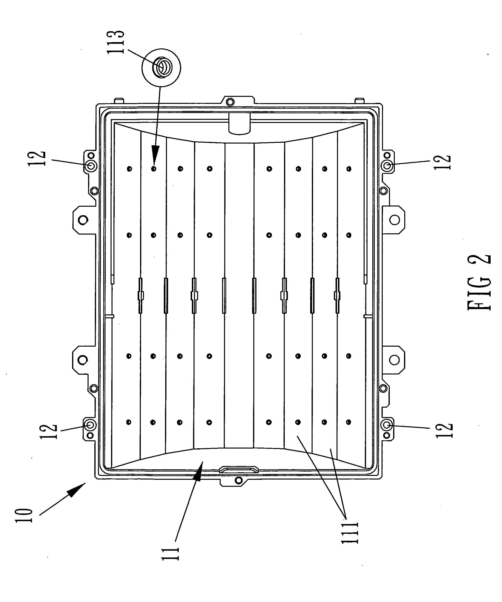
[0018]First, with references to FIG. 13, the light base 10 of the invention has a concaved room 11 in one side, which is used to contain multiple LED modules 20 (as shown in FIG. 4˜6). Along the central line of the concaved room 11, each side has at least four rectangular plains 111. Rectangular plains 111 are in parallel adjacent to one another in its longitudinal direction, and they are U-curved formed in sectional view. At the rim of the concaved room 11 is circled by a rim groove 112 used to fit with a rubber gasket (not shown in the figures), so that a transparent cover 50 (as shown in FIG. 7 and 8) can fit tightly onto the rim groove 112 to completely seal the concaved room 11, and thus no rain or any insect can enter into the concaved room 11 to interfere with LED performances; also shown in FIG. 7 and 8, at outer wall of the light base 10 sets symmetrical fixing holes 12 so that L-shaped bolts 121 can rotate against them to lock and position the transparent cover 50 firmly o...


PUM


Abstract

This invention is to propose a light base structure of high-power LED street lamp that has a concaved room with symmetrical rectangular plains inside. With the design, high-power LED modules can be mounted on the base and emit light with various interlacing included angles and at interlacing locations. The included angle of the normal lines of the outermost two symmetrical rectangular plains is designed between 60-140 degrees. The purpose of this invention is to produce optimal optical effects, including broadening lighted range and enhancing light brightness and uniformity in effective lighted area.

Description

FIELD ON THE INVENTIONBACKGROUND OF THE INVENTION[0001]In recent years, the brightness of LED has been advancing, greatly making its market application wider. Take prior art, for example, its features include: a light base that can mount multiple LED modules, and the base body convex out at same direction as the LED lights. At the convex side of the base facilitates multiple symmetrical mounting faces, the included angle of the first pair of symmetrical mounting faces (the pair closest to the central line of the base) is between 76˜86 degrees, the included angle of the second pair of symmetrical mounting faces (the pair secondly closest to the central line of the base) is between 49˜59 degrees, and the included angle of the third pair of symmetrical mounting faces (the pair 3rdly closest to the central line of the base) is between 37˜47 degrees. Although such structure makes lighted range bigger, its actual performance on lighting effects is still controversial This is because the i...

Claims


Application Information

Patent Timeline
IPC IPC(8): F21V29/00F21V15/01
CPCF21S2/005F21V15/01F21V19/001F21V29/004F21V29/717F21W2131/103F21Y2101/02Y02B20/72F21Y2113/00F21V29/2212F21Y2115/10F21V29/71F21V29/74
Inventor HO, YEN-WEI
Owner GENIUS ELECTRONICS OPTICAL CO LTD
Why Eureka
Try Eureka