Vehicle brake device

Active Publication Date: 2016-04-28
HONDA MOTOR CO LTD
View PDF8 Cites 5 Cited by
  • Summary
  • Abstract
  • Description
  • Claims
  • Application Information

AI Technical Summary

Benefits of technology

The invention allows for control during braking to optimize the buildup effect based on the vehicle speed and the brake pedal depression stroke.

Problems solved by technology

However, the factors that may affect the brake control include, in addition to the vehicle speed, changes in the braking operation amount (brake pedal depression stroke) controlled by the vehicle operator.
The conventional brake control may not be able to cope with the case where the braking operation amount changes during the course of a braking operation.

Method used


Image

  • Vehicle brake device
  • Vehicle brake device
  • Vehicle brake device

Examples


Embodiment Construction

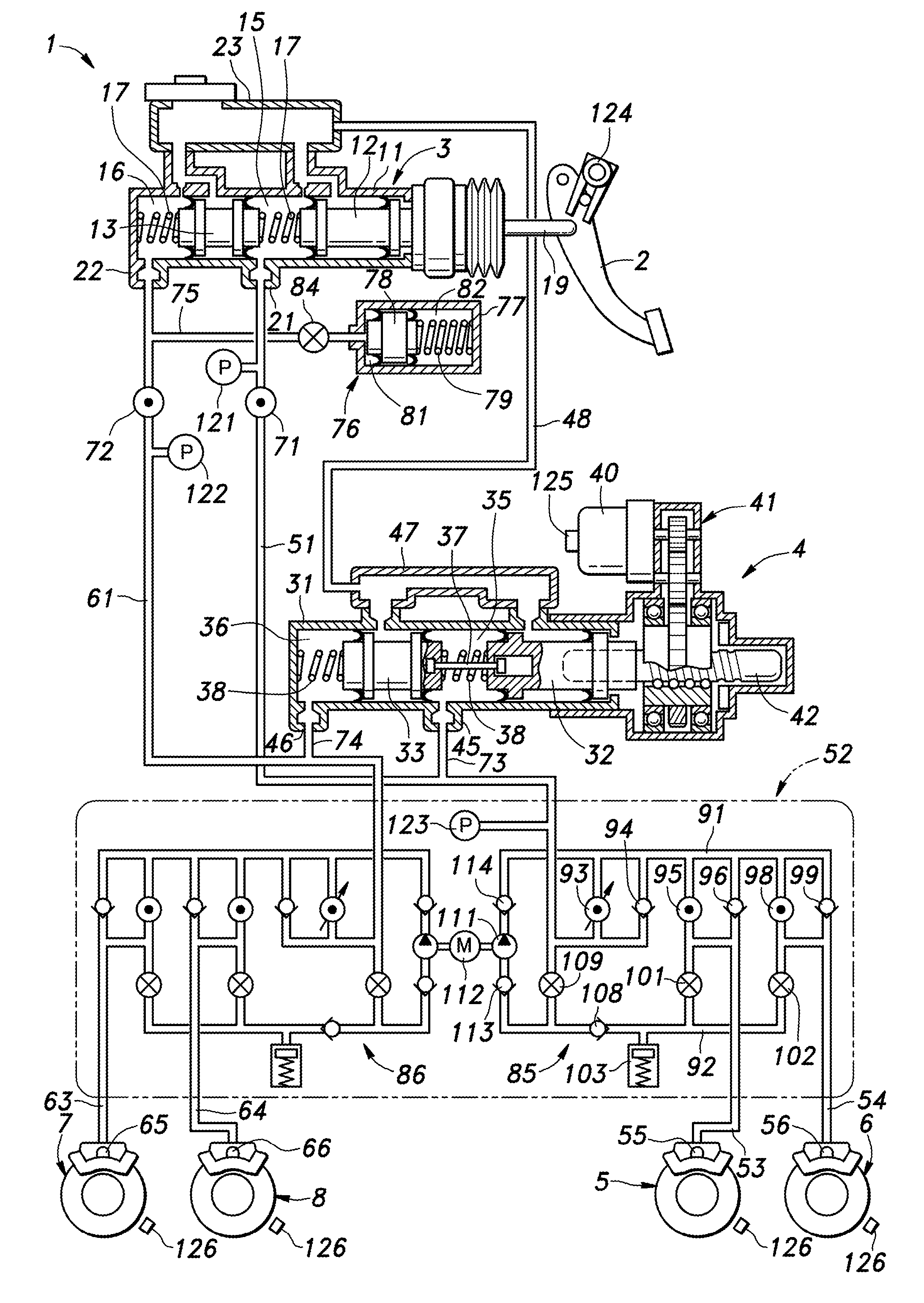
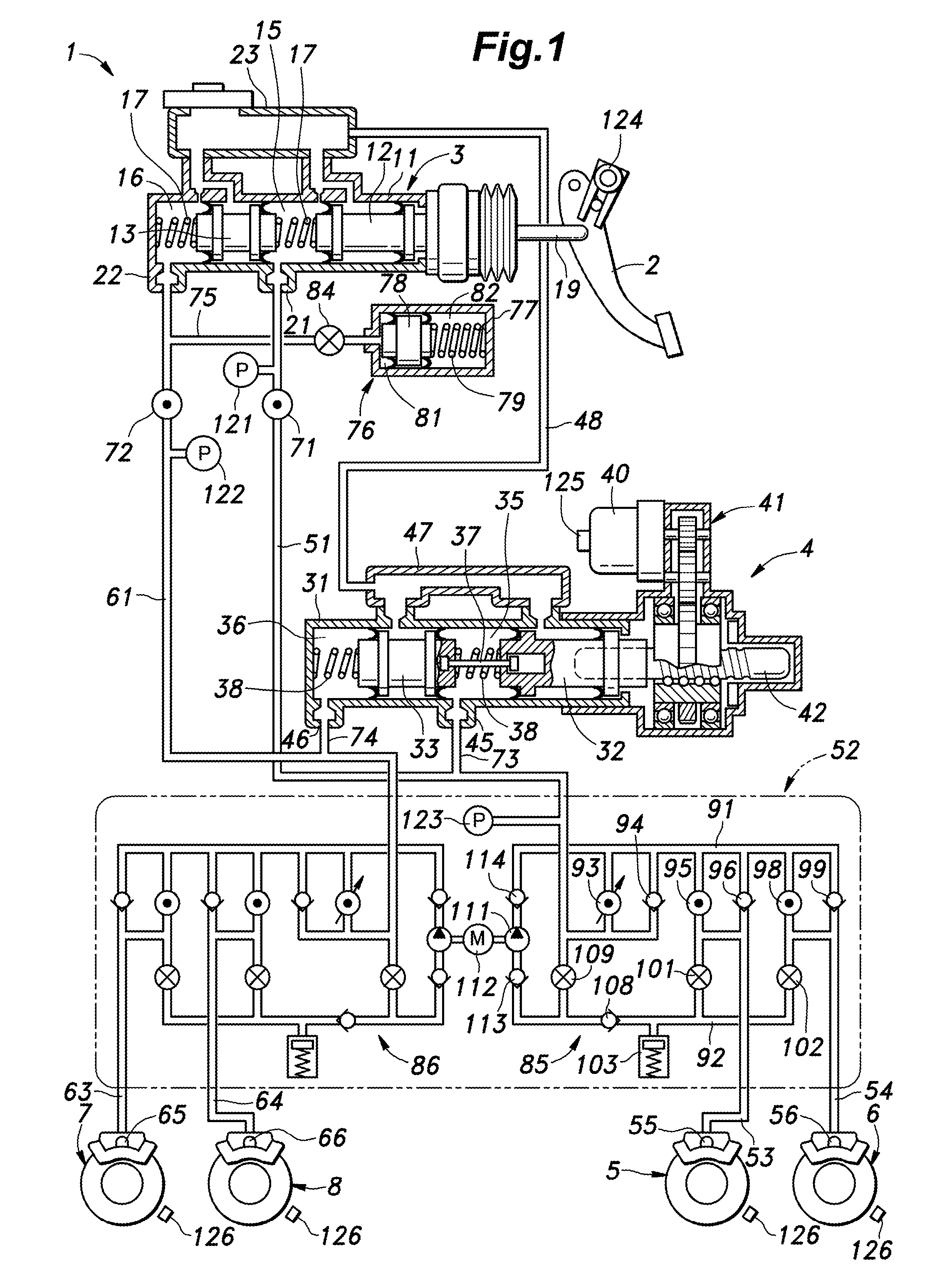
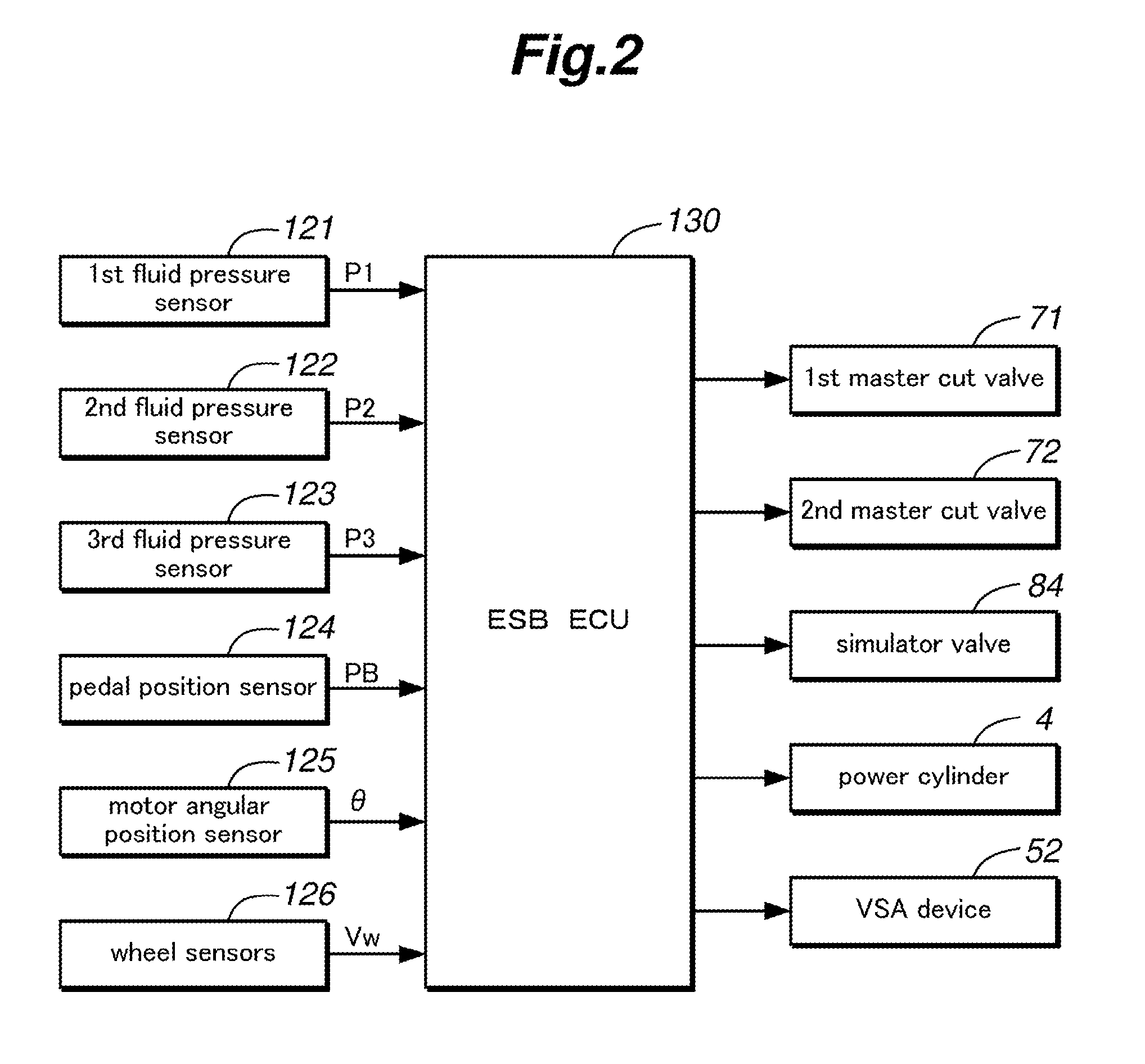
[0026]A preferred embodiment of the present invention is described in the following with reference to the appended drawings. FIG. 1 is a view showing a hydraulic circuit of a vehicle brake device 1, and FIG. 2 is a block diagram showing a control system of the vehicle brake device. As shown in FIGS. 1 and 2, the vehicle brake device of the illustrated embodiment includes a brake pedal 2 serving as a braking operation member pivotally supported on the vehicle body, a master cylinder 3 and a power cylinder 4 for producing a hydraulic pressure in dependence on the depression stroke of the brake pedal 2, and disk brakes 5, 6, 7 and 8 that are actuated by the hydraulic pressure supplied by the master cylinder 3 or the power cylinder 4 thereto.

[0027]The master cylinder 3 consists of a tandem cylinder including a cylindrical master housing 11, a first master piston 12 and a second master piston 13 slidably received in the master housing 11. The first master piston 12 is positioned axially ...


PUM


Abstract

A target control value of the brake fluid pressure generated in dependence on the braking operation amount is set by using a first coefficient determined in dependence on the vehicle speed in an early phase of a braking operation performed by a vehicle operator and a second coefficient determined in dependence on the braking operation amount and the vehicle speed during a later braking action. The increase in the braking force for the buildup control can be restrained in an early phase of the braking operation so that the onset of deceleration in an early phase of the braking action for the given braking operation can be made gradual in a manner corresponding to the vehicle speed while a favorable buildup control is achieved by increasing the deceleration as the vehicle speed decreases in the course of the braking action.

Description

FIELD OF THE INVENTION[0001]The present invention relates to a vehicle brake device, and in particular to a vehicle brake device that produces a braking force by using an electric actuator.BACKGROUND OF THE INVENTION[0002]Conventionally, a vehicle brake device using a brake-by-wire technology is known which uses a hydraulic cylinder actuated by an electric actuator such as an electric motor to produce a brake pressure. It is known that the braking force tends to be reduced toward a latter part of a braking action when the brake pedal is depressed by a constant stroke owing to the mechanical property of the brake device, and this may prevent the vehicle from slowing down at a deceleration intended by the vehicle operator. Therefore, the vehicle operator has to depress the brake pedal further in order to achieve a desired deceleration, and this may complicate the braking operation for the vehicle operator.[0003]In the case of the brake-by-wire system which uses an electric actuator co...

Claims


Application Information

Patent Timeline
IPC IPC(8): B60T13/66B60T13/14B60T13/68B60T13/74B60T7/04B60T8/40
CPCB60T13/662B60T7/042B60T13/146B60T13/686B60T13/745B60T8/4081B60T2201/03B60T2220/04
Inventor ISHINO, KEISUKEOKADA, SHUICHIAKAMINE, KOHEIHATANO, KUNIMICHI
Owner HONDA MOTOR CO LTD
Why Eureka
Try Eureka