Apparatus for cooling inverter

Active Publication Date: 2015-03-05
LSIS CO LTD
View PDF5 Cites 7 Cited by
  • Summary
  • Abstract
  • Description
  • Claims
  • Application Information

AI Technical Summary

Benefits of technology

[0024]The apparatus for cooling inverter according to exemplary embodiments of the present disclosure has an advantageous effect in that air flow can be adjusted by separating a flow part in response to heat radiation amount of electric elements arranged inside a housing of a cooling apparatus, whereby an optimum heat radiation effect can be accomplished, and heat radi

Problems solved by technology

In general, an inverter, or a power inverter, is an electrical power converter that changes DC (Direct Current) to AC (Alternating Current) at any required voltage and frequency for controlling an induction motor,

Method used


Image

  • Apparatus for cooling inverter
  • Apparatus for cooling inverter
  • Apparatus for cooling inverter

Examples


Example

[0033]Hereinafter, various example embodiments of the present disclosure will be described in more detail with reference to the accompanying drawings. Thus, the disclosure described herein is intended to embrace all such alternatives, modifications, variations and applications as may fall within the spirit and scope of the appended claims.

[0034]Hereinafter, an apparatus for cooling inverter (hereinafter an apparatus for cooling inverter may be referred to as inverter cooling apparatus, or simply as apparatus) according to exemplary embodiments of the present disclosure will be described in detail with reference to the accompanying drawings.

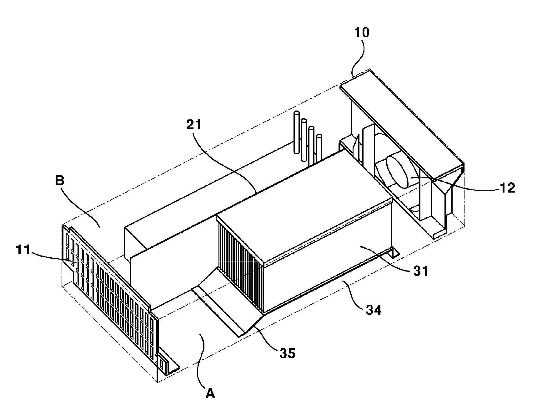
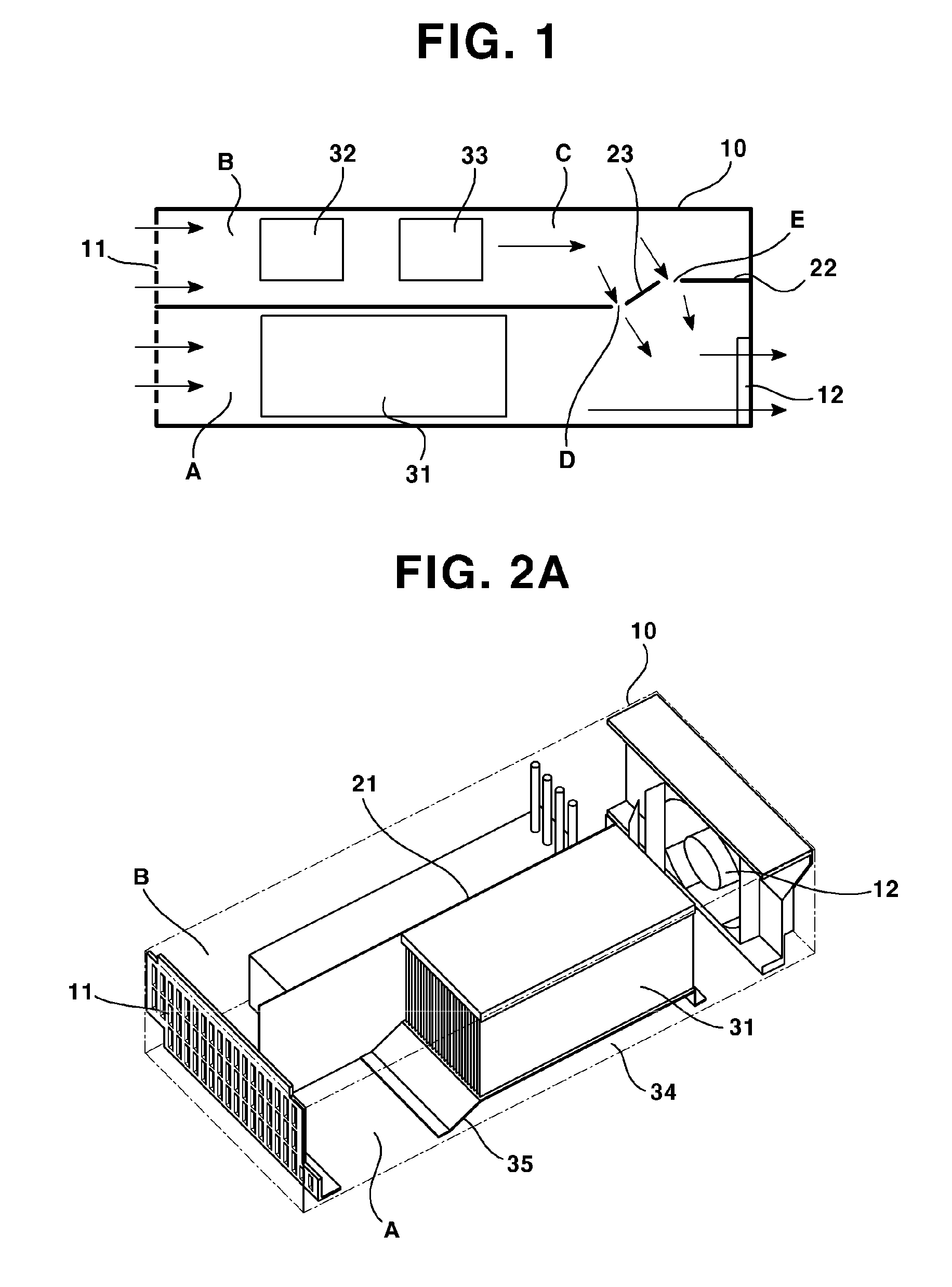
[0035]FIG. 1 is a schematic plan view illustrating a structure of an apparatus for cooling inverter according to a first exemplary embodiment of the present disclosure, where an interior of housing (10) is illustrated from an upper side.

[0036]Referring to FIG. 1, the apparatus is arranged inside a housing (10) of square shape, where an inlet (11) ...


PUM


Abstract

An apparatus for cooling inverter is disclosed, whereby an optimum heat radiation effect can be accomplished, because a flow part is divided in response to heat generation amount of an electric element arranged inside a housing to adjust an air flow.

Description

CROSS-REFERENCE TO RELATED APPLICATIONS [0001]Pursuant to 35 U.S.C. §119(a), this application claims the benefit of earlier filing date and right of priority to Korean Patent Application No. 10-2013-0103758, filed on Aug. 30, 2013, the contents of which are all hereby incorporated by reference herein in its entirety.BACKGROUND OF THE DISCLOSURE [0002]1. Field of Endeavor[0003]The present disclosure relates to an apparatus for cooling an inverter.[0004]2. Background[0005]In general, an inverter, or a power inverter, is an electrical power converter that changes DC (Direct Current) to AC (Alternating Current) at any required voltage and frequency for controlling an induction motor, but the inverter has problems of requiring a relatively large fan and a heat radiating member for forcibly discharging heat generated from elements inside the inverter, thereby increasing the size of the inverter. Conventionally, an inverter cooling structure is such that an inlet and an outlet are parallel...

Claims


Application Information

Patent Timeline
IPC IPC(8): H05K7/20
CPCH05K7/20009H05K7/20909H01L23/467H01L2924/0002H02M7/003H01L2924/00H05K7/20172H05K7/2089
Inventor HWANG, SOO YONG
Owner LSIS CO LTD
Why Eureka
Try Eureka