Engine controller and associated operating method

Inactive Publication Date: 2006-06-06
DAIMLER AG
View PDF11 Cites 2 Cited by
  • Summary
  • Abstract
  • Description
  • Claims
  • Application Information

AI Technical Summary

Benefits of technology

[0004]In spark ignition engines, fuel tank venting devices are also known in which the fuel which is vaporizing in the fuel container is taken up by an activated carbon filter and buffered. This buffering of the vaporizing fuel in an activated carbon filter advantageously prevents fuel vaporizations from being able to contaminate the surrounding air. However, the absorptive capacity of such activated carbon filters is limited so that, when a predefined degree of loading is reached, the activated carbon filter is purged with fresh air and the stored fuel passes into the intake tract of the spark ignition engine and is subsequently burnt. During this purging of the activated carbon filter, the spark ignition engine changes over temporarily from the normal operating mode of a regulated lambda value into a different operating mode in which the fuel / air ratio can deviate from the setpoint value. In the known spark ignition engines, this changeover of the operating mode takes place at predefined time intervals so that the absorptive capacity of the activated carbon filter is not exceeded.
[0010]The degree of loading of the activated carbon filter is preferably determined by changing over into the fuel tank venting mode in a timed fashion, the activated carbon filter being purged with fresh air and as a result regenerated. The vaporizations of fuel, which are purged from the activated carbon filter, depending on the degree of loading of the activated carbon filter, cause the fuel / air mixture to be enriched, which is sensed by means of a lambda probe. The change in the fuel / air ratio during the regeneration of the activated carbon filter therefore permits the degree of loading of the activated carbon filter to be determined.
[0012]In another variant of the invention, the changeover from the normal mode or lean mode of the internal combustion engine into an operating mode in which the fuel / air ratio is adapted is controlled. In modern spark ignition engines with an exhaust gas catalytic converter, the fuel / air ratio is regulated because the purification effect of exhaust gas catalytic converters depends on the fuel / air ratio, and is also satisfactory only within a highly limited value range (referred to as the catalytic converter window) of the fuel / air ratio for the different exhaust gas components comprising hydrocarbon, nitrogen oxide and carbon monoxide. However, the regulating dynamics during the regulation of the fuel / air ratio decline in proportion to the magnitude of the error to be eliminated, with the result that the regulation of the fuel / air ratio is usually combined with a pilot control. The pilot control predefines a fuel / air ratio as a working point for the regulation of the fuel / air ratio, with the result that the regulator then only has to eliminate small errors, and therefore has good regulating dynamics. The adaptation of the fuel / air ratio has the function of setting the pilot control in such a way that, as far as possible, minimum errors are required to be eliminated at the working point of the regulator in order to achieve regulating dynamics which are as good as possible.

Problems solved by technology

However, the absorptive capacity of such activated carbon filters is limited so that, when a predefined degree of loading is reached, the activated carbon filter is purged with fresh air and the stored fuel passes into the intake tract of the spark ignition engine and is subsequently burnt.
However, it is a disadvantage of this timed changeover of the operating mode that the quantity of vaporizing fuel also depends on other variables, such as, for example, the fuel temperature and fuel pressure.
The timed changeover of the operating mode therefore leads to unsatisfactory results.

Method used


Image

  • Engine controller and associated operating method
  • Engine controller and associated operating method
  • Engine controller and associated operating method

Examples


Embodiment Construction

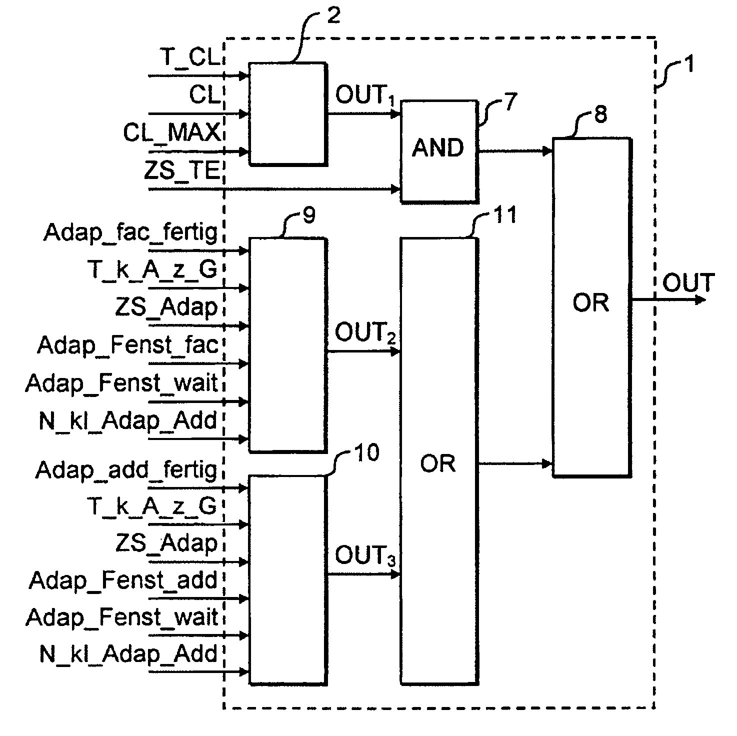
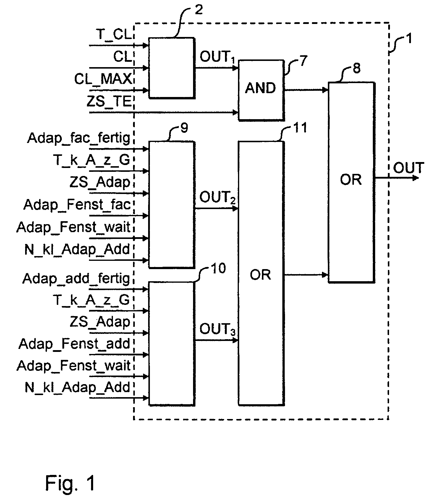
[0024]The block circuit diagram in FIG. 1 shows a control unit 1 according to the invention, which is used in an electronic engine controller for a spark ignition engine in order to disable a lean mode of the spark ignition engine if the spark ignition engine is to change over into another operating mode. The control unit 1 therefore has a binary signal output for disabling or respectively enabling the lean mode, a control signal OUT being output at said signal output and the control signal OUT assuming a high level to disable the lean mode and a low level to enable the lean mode.

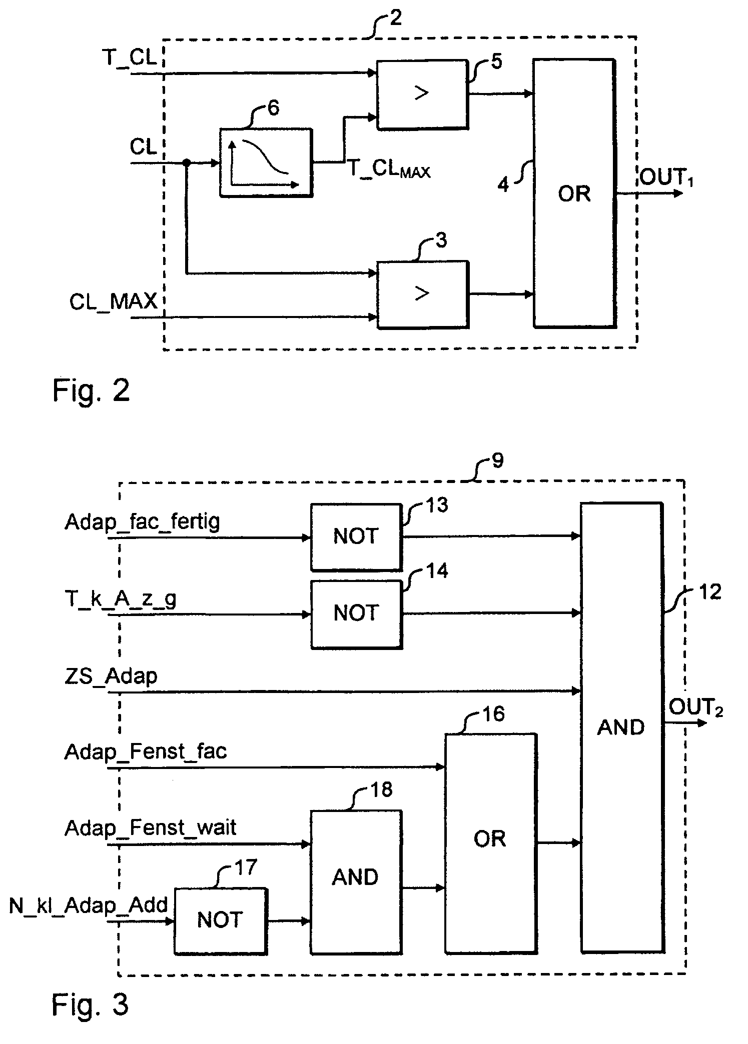
[0025]The lean mode is disabled, for example, if an activated carbon filter has to be regenerated in the fuel tank venting operation. For this purpose, the control unit 1 has an evaluation unit 2 which is illustrated in detail in FIG. 2 and picks up, at the input end, a previously determined degree of loading CL of the activated carbon filter and a measured time period T_CL since the last regeneration of th...


PUM


Abstract

Operating method and apparatus for operating an engine controller for an internal combustion engine, including operating in a first operating mode, acquiring at least one state variable (CL, Adap_Fenst_fac, Adap_Fenst_Add) of the internal combustion engine and changing over from the first operating mode into a second operating mode. The changeover from the first operating mode into the second operating mode take place as a function of the determined state variable (CL, Adap_Fenst_fac, Adap_Fenst_Add) of the internal combustion engine.

Description

BACKGROUND AND SUMMARY OF THE INVENTION[0001]This application claims the priority of German application DE 103 08 650.1, filed 27 Feb. 2003, which is expressly incorporated by reference herein.[0002]The invention relates to an operating method for operating an engine controller and to a corresponding engine controller.[0003]Modern spark ignition engines generally have a three-way catalytic converter for purifying the exhaust gases. The fuel / air ratio in the exhaust gas is regulated to a value of approximately λ≈1 by means of a lambda probe arranged in the stream of exhaust gases, in order to bring about an optimum purification effect of the three-way catalytic converter for the various components of the exhaust gases.[0004]In spark ignition engines, fuel tank venting devices are also known in which the fuel which is vaporizing in the fuel container is taken up by an activated carbon filter and buffered. This buffering of the vaporizing fuel in an activated carbon filter advantageous...

Claims


Application Information

Patent Timeline
IPC IPC(8): F02D41/14F02D41/00F02D41/30F02M25/07F02M25/08G05B13/02
CPCF02D41/0032G05B13/021F02D41/2454F02D41/0045F02D41/2441F02D41/3076F02M25/08
Inventor HANNBECK VON HANWEHR, RAINERHEIDENFELDER, HANS-DIETER
Owner DAIMLER AG
Why Eureka
Try Eureka