Photoacoustic Apparatus, and Probe for Receiving Photoacoustic Waves

a technology of photoacoustic waves and probes, which is applied in the direction of instruments, ultrasonic/sonic/infrasonic image/data processing, fluorescence/phosphorescence, etc., can solve the problems of difficult to provide a large amount of light to a deep tissue in the living body, difficult to obtain information on a deep portion of a specimen, and rapid attenuation of light irradiated to the specimen. , to achieve the effect of improving

Active Publication Date: 2010-03-04
CANON KK
View PDF6 Cites 103 Cited by
  • Summary
  • Abstract
  • Description
  • Claims
  • Application Information

AI Technical Summary

Benefits of technology

[0020]According to the present invention, it becomes possible to cause the light diffused in a living body and radiated out of the living body to reenter the living body under the action of reflection of a reflection member. As a result of this, the efficiency for light utilization is improved, so it becomes possible to make a medical diagnosis at a deeper than conventional position with a limited amount of light.

Problems solved by technology

In photoacoustic imaging, there is a problem that it is difficult to obtain information on a deep portion of a specimen because of the attenuation of light due to the optical absorption in a living body.
However, the light irradiated to the specimen is rapidly attenuated in the specimen due to the dispersion and absorption thereof.
Furthermore, in the case of a human body, a safety restriction on the amount of light allowed to be irradiated thereto is provided by standards, so it is difficult to provide a large amount of light to a deep tissue in the living body.
Therefore, it becomes difficult to obtain photoacoustic waves from a deep portion of the living body.
However, this is not effective use of the diffused light which is the light radiated out of the living body after entering the specimen.
In addition, in this case, it is necessary that the specimen should be located at the focus of the spheroid, and a large probe such as an array probe or the like interrupts the light and hence can not be used.
Furthermore, a signal is also unable to be detected while scanning the probe.
Thus, since large restrictions arise on the use of the technique of this document, the application thereof to general-purpose imaging apparatuses is difficult.
That is, the construction of the first non-patent document can not utilize the optical energy so effectively, and it is formed only for the purpose of noise removal.

Method used


Image

  • Photoacoustic Apparatus, and Probe for Receiving Photoacoustic Waves
  • Photoacoustic Apparatus, and Probe for Receiving Photoacoustic Waves
  • Photoacoustic Apparatus, and Probe for Receiving Photoacoustic Waves

Examples


first embodiment

Fundamental Configuration

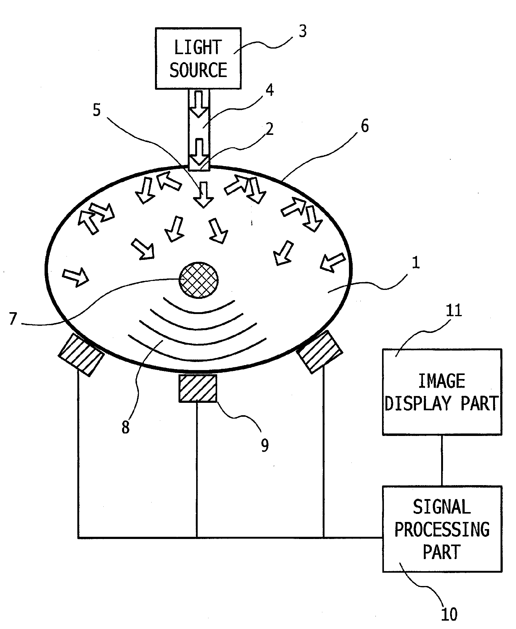
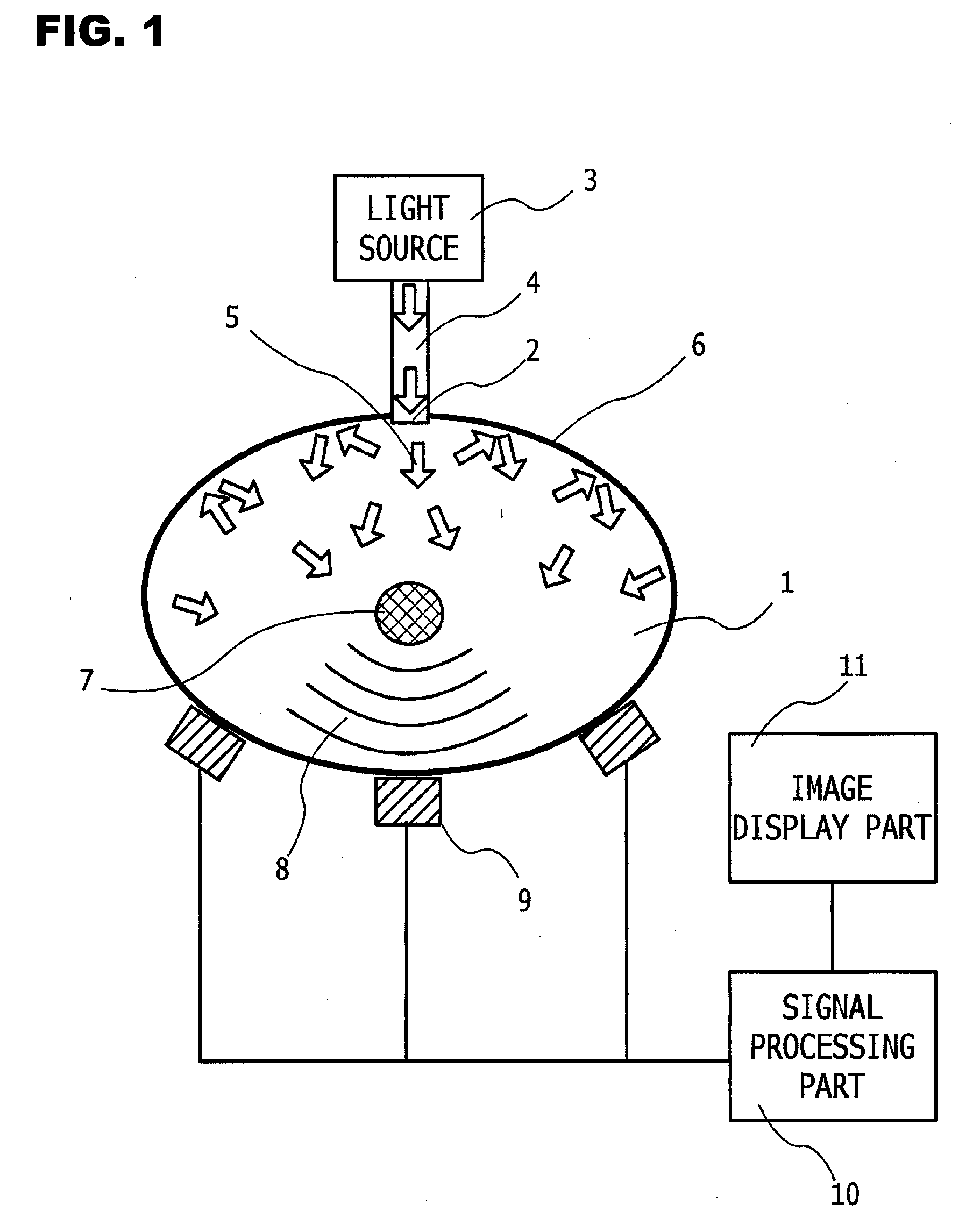
[0037]FIG. 1 shows a view explaining an example of the construction of a biological information imaging apparatus in a first embodiment of the present invention. In FIG. 1, a reference numeral 1 denotes a living body as a specimen, 2 a light radiation point, 3 a light source, 4 an optical fiber, 5 light propagating in the living body, 6 a light reflection member, 7 a light absorber, 8 an acoustic wave, and 9 acoustic wave receivers. In addition, the biological information imaging apparatus can include a signal processing part 10 and an image display part 11, which, however, may be provided separately.

[0038]The biological information imaging apparatus of this embodiment makes it possible to image the concentration distribution of substances forming a living body tissue obtained from optical property values in the living body and their information for diagnosis of a malignant tumor, a vascular disease, etc., and for the follow-up of a chemical treatment, etc.

[...

second embodiment

Probe

[0057]Next, reference will be made to another embodiment of the present invention in which a construction example of the above-mentioned probe that can realize effective use of light and a biological information processing apparatus using such a probe, while using the accompanying drawings. In this embodiment, it is featured that a light reflection member is provided on a probe which includes an acoustic wave receiver. FIG. 5 illustrates a view explaining the construction example of the biological information processing apparatus in this embodiment.

[0058]The biological information processing apparatus of this embodiment makes it possible to image optical property values in a living body and the concentration distribution of substances that constitutes the living body tissue obtained from the information of these, for diagnosis of a malignant tumor, a vascular disease, etc., and for the follow-up of a chemical treatment, etc.

[0059]The biological information processing apparatus ...

first example

[0082]As a first example, a simulation was made in which a reflection member having a reflection factor of 100% was used as a reflection member which constitutes part of a biological information imaging apparatus. A case was taken in which light was caused to enter a cube with a side of 4 cm imitating a living body. The simulation calculated a well-known optical diffusion equation by means of a finite element method. For optical constants in the cube, an absorption coefficient was set to 0.1 [cm−1], and an effective scattering coefficient was set to 10 [cm−1]. A circular-shaped continuous light having a diameter of 1 mm was irradiated to the center of a bottom surface of the cube (the center of a square) at 10 mW. A boundary condition was set such that in the case of the presence of the reflection member, diffused light is totally reflected (a reflection factor of 100%), and in the case of the absence of the reflection member, diffused light substantially totally transmits or passes...


PUM

PropertyMeasurementUnit
refractive indexaaaaaaaaaa
widthaaaaaaaaaa
widthaaaaaaaaaa

Abstract

A photoacoustic apparatus obtains information on a specimen by receiving photoacoustic waves which are generated from the specimen resulting from light irradiated to the specimen. The apparatus includes a light source for irradiating light to the specimen, an acoustic wave receiver for receiving the photoacoustic waves, and a light reflection member for causing the light, which is radiated out of the specimen by optical diffusion thereof after having entered an interior of the specimen from the light source, to reenter the interior of the specimen, wherein the light reflection member allows elastic waves to pass therethrough. As a result, a photoacoustic apparatus and a probe are provided which can confine scattered light from the specimen into the specimen, and which can reliably prevent photoacoustic waves from being generated from a receiving element region of the probe by the scattered light.

Description

BACKGROUND OF THE INVENTION[0001]1. Field of the Invention[0002]The present invention relates to a photoacoustic apparatus which obtains information on a specimen by receiving photoacoustic waves generated from the specimen resulting from light irradiated to the specimen, and it also relates to a probe for receiving the photoacoustic waves.[0003]2. Description of the Related Art[0004]As one of the optical imaging techniques, there has been proposed photoacoustic tomography (PAT) (see a first non-patent document). The photoacoustic tomography is a technique in which a specimen is irradiated with pulsed light generated from alight source, and acoustic waves are detected which are generated from a living body tissue that has absorbed the energy of the light propagated and diffused in the interior of the specimen, whereby those acoustic waves or signals are subjected to analytical processing to visualize the information relevant to optical property values in the interior of the specimen...

Claims


Application Information

Patent Timeline
Patent Type & Authority Applications(United States)
IPC IPC(8): G01N21/64A61B8/08G01N29/00G01N29/24
CPCA61B5/0059G01N2021/1706G01N21/1702A61B5/0095A61B8/4281
Inventor NAKAJIMA, TAKAOFUKUTANI, KAZUHIKOASAO, YASUFUMINANAUMI, RYUICHI
Owner CANON KK
Why Eureka
Try Eureka