Glass thin layer optic disk structure and process

A disc structure and glass technology, which is applied in optical recording/reproduction, instrumentation, data recording, etc., can solve problems such as vibration, poor wear resistance, recording errors, etc., to achieve less vibration, improve disc rigidity, and long life Effect

Inactive Publication Date: 2006-06-07
崔龙华
View PDF0 Cites 2 Cited by
  • Summary
  • Abstract
  • Description
  • Claims
  • Application Information

AI Technical Summary

Problems solved by technology

Due to the poor abrasion resistance of the resin during use, all kinds of resin discs are not only afraid of touching, but also afraid of grinding, rubbing and scratching, which often cause various scars unexpectedly.
After repeated use, there are often scratches and damage to the read-out surface of the disc due to machinery, which

Method used


Image

  • Glass thin layer optic disk structure and process
  • Glass thin layer optic disk structure and process
  • Glass thin layer optic disk structure and process

Examples


Embodiment Construction

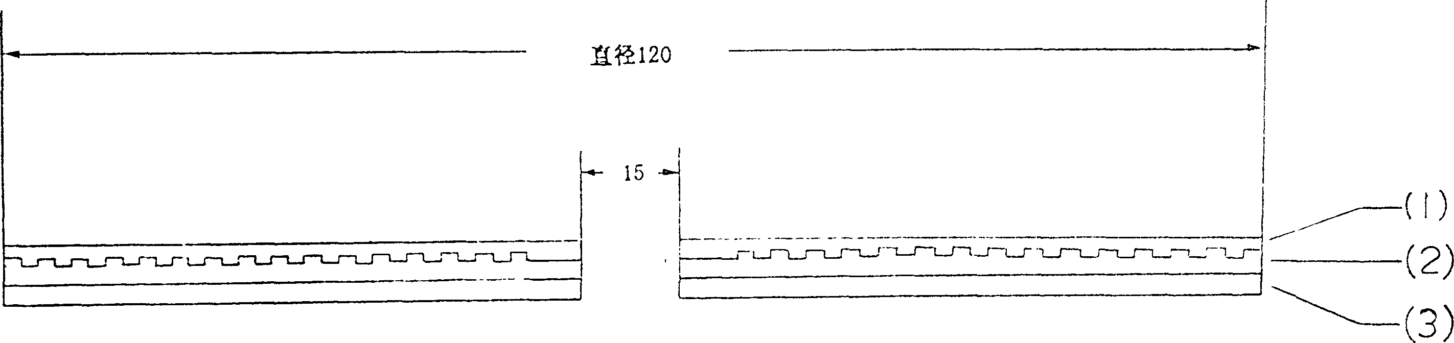
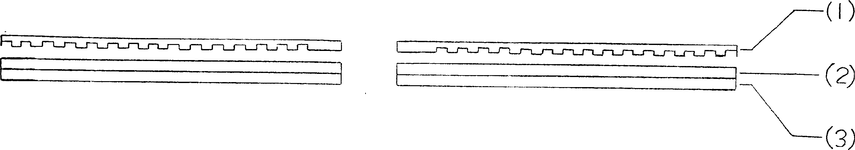
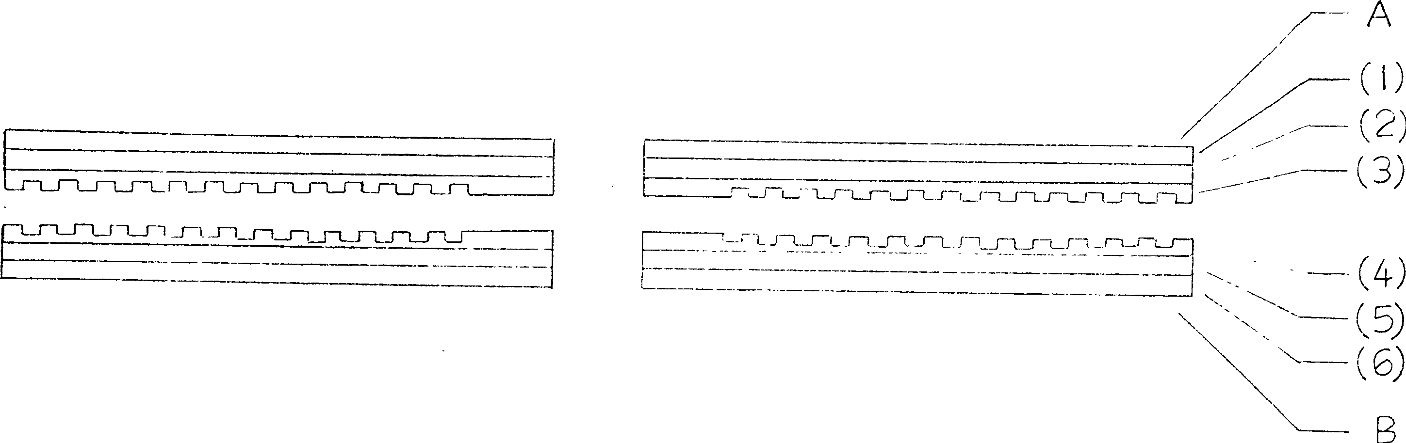
[0015] exist Figure 4 (1)-(4) are traditional optical disc technology, Figure 4 -(1) is die-cast, Figure 4 -(2) for copying, Figure 4 -(3) is a gold or aluminum layer, Figure 4 -(4) is the protection of the marking signal surface. After this process, another process is added. Figure 4 -(5) is to add a thin layer of quartz glass on the surface of the resin disc such as Figure 4 -(A). The thin layer of quartz glass and the traditional resin disc are bonded with an epoxy resin adhesive, wherein the thickness of the resin disc is reduced from the original 1.2mm to 1.0mm, and the thickness of the thin layer of quartz glass is 0.2mm, which just realizes the manufacturing process of the present invention .

[0016] exist figure 2 Middle: The manufacturing process of DVD-5 quartz glass layer disc and Figure 4 The same as described in (1)-(5) optical disk manufacturing process, but the parameters are changed, such as reducing the thickness of the resin optical disk fr...


PUM

PropertyMeasurementUnit
Layer thicknessaaaaaaaaaa

Abstract

The present invention aims at making resin CD touch resistant and wear resistant, and the technological scheme is that one very thin glass layer is adhered to the surface of resin CD to make the CD possess clear replaying, less scratch, long service life, high rigidity and less vibration under high speed rotation while keeping the merits of available CD.

Description

technical field [0001] The invention relates to various tree-finger optical discs, in particular to the fields of manufacture, structure and technology of resin optical discs. Background technique [0002] The material of the existing LD, VCD, CD, DVD, AOD, BLU-ray (high-definition disc), FMD (fluorescent multi-layer disc) and software disc, etc. is usually resin. Due to the poor wear resistance of the resin during use, various resin discs are not only afraid of touching, but also afraid of grinding, rubbing, and scratching, which often cause various scars unexpectedly. After repeated use, scratches and damage to the readout surface of the optical disc often occur due to mechanical damage, which causes errors in reading data. For this reason, recording errors due to surface damage of the optical disc make the optical disc unusable. In addition, due to the low rigidity of the resin, the optical disc vibrates when it rotates at high speed, which ...

Claims


Application Information

Patent Timeline
IPC IPC(8): G11B7/254
Inventor 崔龙华
Owner 崔龙华
Why Eureka
Try Eureka