Antenna joint device capable of adjusting direction

A joint device and direction adjustment technology, which is applied to antenna supports/installation devices, antennas, electrical components, etc., can solve the problems of looseness and falling off between the antenna connector and the surface of the casing, inconvenient assembly, and difficulty in improving yield.

Inactive Publication Date: 2006-06-21
E-TEN
View PDF0 Cites 3 Cited by
  • Summary
  • Abstract
  • Description
  • Claims
  • Application Information

AI Technical Summary

Problems solved by technology

Since the aforementioned antenna connecting seat is fixed on the surface of the casing, the stress generated when the external antenna is adjusted to the direction of rotation relative to the antenna connecting seat will often cause loosening and falling off between the antenna connecting seat and the surface of the casing, resulting in The great problem of electronic devices in sending and receiving signals
Furthermore, since the connection between the antenna connection seat and the circuit board may only be connected to each other by a signal line or a contact shrapnel, it is often caused by loosening of the line contacts after a long period of use, resulting in signal loss on the transceiver. adverse effects
In addition, since the antenna connection base and the circuit board are soldered to each other by signal wires or contact springs, it may also cause inconvenience in assembly during the production process, or it may be difficult to improve the yield rate of production

Method used


Image

  • Antenna joint device capable of adjusting direction
  • Antenna joint device capable of adjusting direction
  • Antenna joint device capable of adjusting direction

Examples


Embodiment Construction

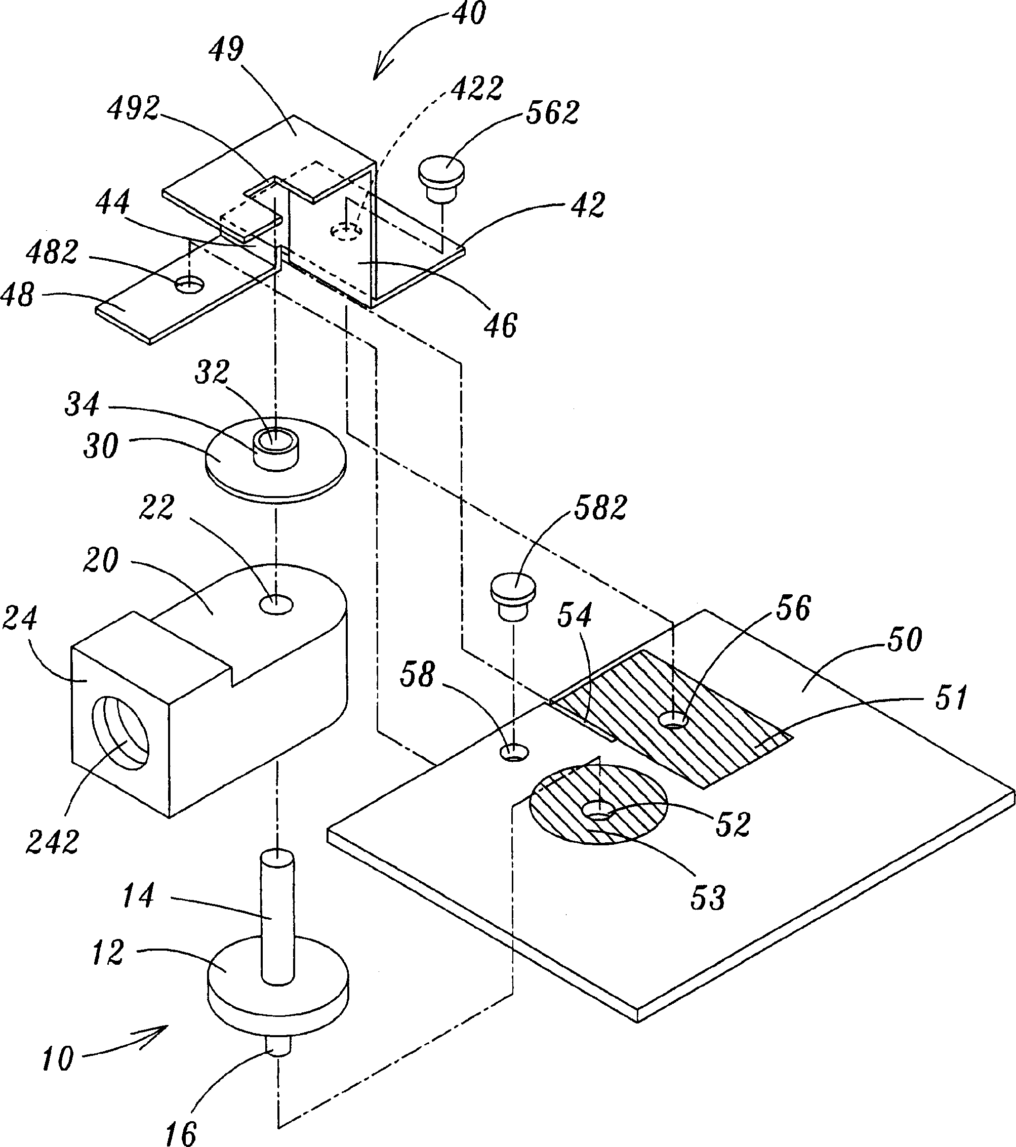
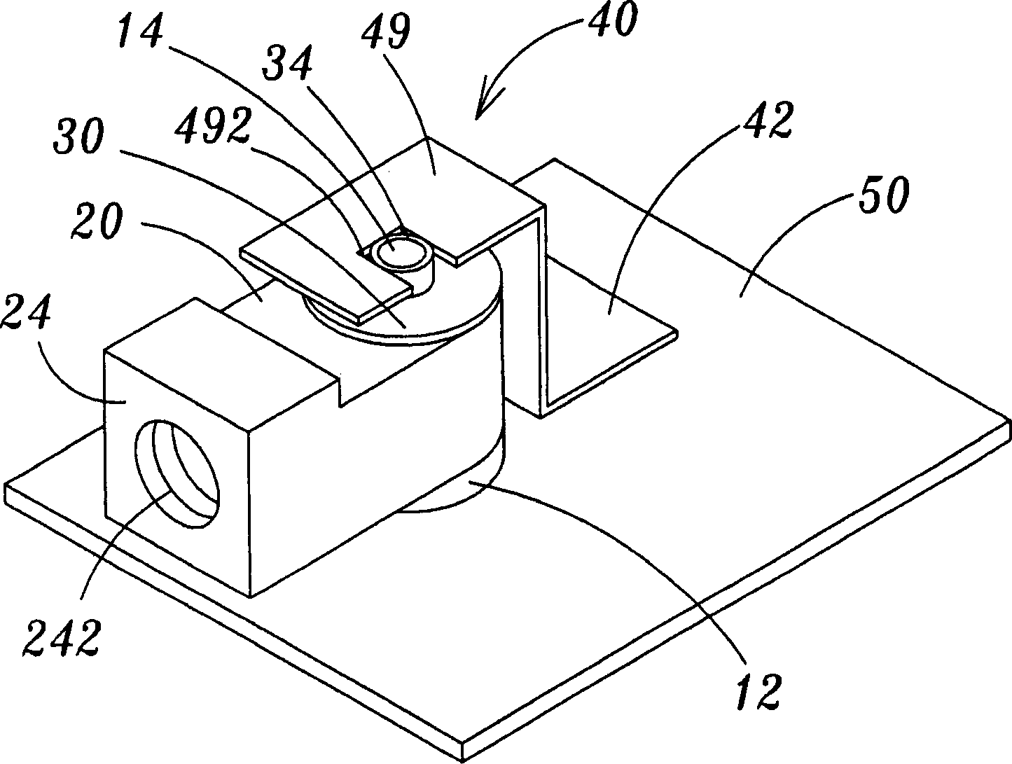
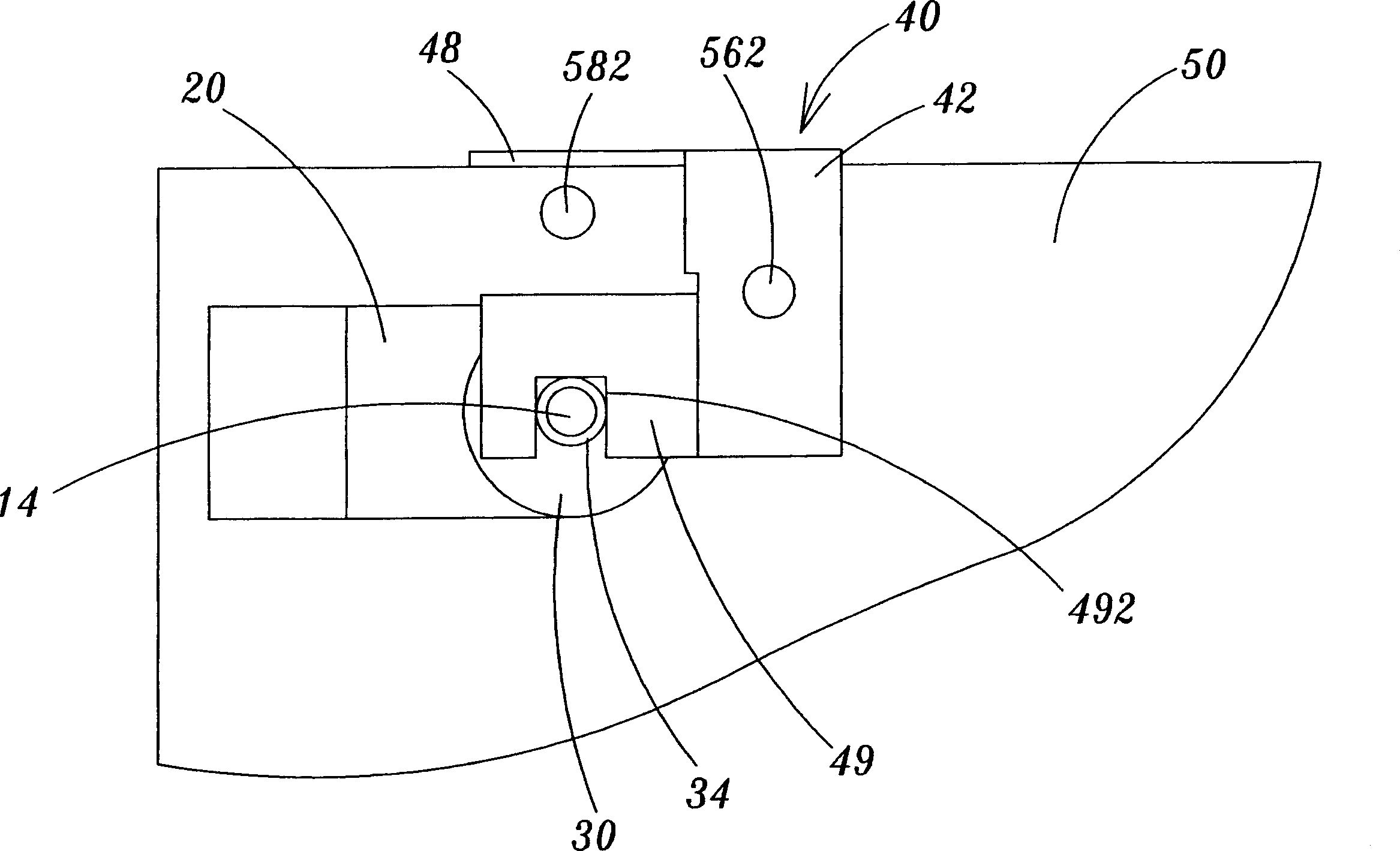
[0046] Please refer to Figure 1 to Figure 3 As shown, the preferred embodiment of the antenna joint device with adjustable direction of the present invention includes a rotating member 10, an antenna joint base 20, a fixed gasket 30 and a fixed assembly 40, wherein the antenna joint base 20 is The shaft is fixed on the rotating part 10, and the fixing gasket 30 is sleeved on the upper end of the rotating part 10, and the rotating part 10 is fixed on a circuit board 50, and the fixing assembly 40 is fixed on the circuit board 50 , and at the same time, the upper end of the fixed gasket 30 is embedded, and the antenna joint base 20 can be assembled on the circuit board 50 through the above-mentioned composition, so that the antenna joint base 20 can be fixed after an external antenna 60 ( Please refer to Figure 4 ), rotate along the shaft 14 of the rotating member 10, so that the position of the antenna connector base 20 can be rotated in the left and right directions to impr...


PUM


Abstract

The invention relates to an antenna terminal device with adjustable direction, which comprises: a rotation member fixed on a circuit board with an axial fixed base and a fixed pad on upper end, and a securing member arranged on said circuit board. This invention can regulate the position of angle rotation of base to increase receive / send effect for wireless signal.

Description

technical field [0001] The invention relates to a direction-adjustable antenna connector device, which refers to an antenna connector device that can adjust the rotation direction and provide an external antenna for fixed connection. Background technique [0002] With the popularization of communication products, the communication antennas used to send and receive various telecommunication signals are gradually integrated into the electronic devices, and the antennas used in the current electronic devices are designed to beautify the appearance of the electronic devices and reduce the The size of the external volume of the electronic device has gradually tended to use a micro-antenna to be installed inside the electronic device, which can not only prevent the antenna body from being exposed outside the body, but also provide a good signal transmission and reception effect. [0003] For some electronic devices that use an external antenna, since the receiving angle of the ext...

Claims


Application Information

Patent Timeline
Patent Type & Authority Applications(China)
IPC IPC(8): H01Q1/12H01Q1/22H01Q3/04
Inventor 陈荣达
Owner E-TEN
Why Eureka
Try Eureka