Rotary compressor

A rotary and compressor technology, applied in rotary piston machines, rotary piston pumps, pump combinations for elastic fluid rotary piston/oscillating piston, etc., can solve the unclear relationship between passage cross-sectional area and oil content , difficulties in the design of confined spaces, etc., to achieve the effect of reducing oil content

Inactive Publication Date: 2006-06-28
HITACHI JOHNSON CONTROLS AIR CONDITIONING INC
View PDF1 Cites 9 Cited by
  • Summary
  • Abstract
  • Description
  • Claims
  • Application Information

AI Technical Summary

Problems solved by technology

However, in a rotary two-stage compressor with high pressure Pd in ​​a sealed space, the relationship between the passage cr

Method used


Image

  • Rotary compressor
  • Rotary compressor
  • Rotary compressor

Examples


Embodiment Construction

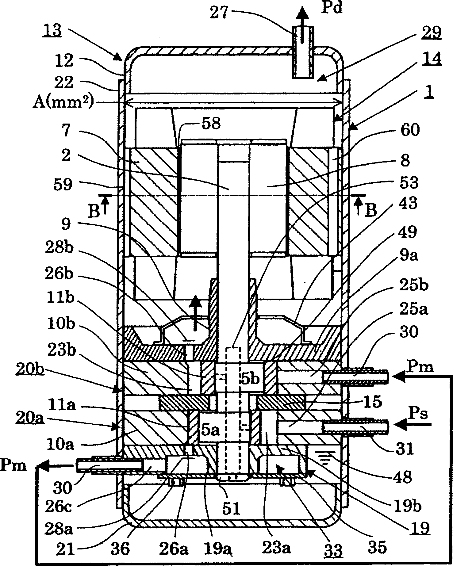
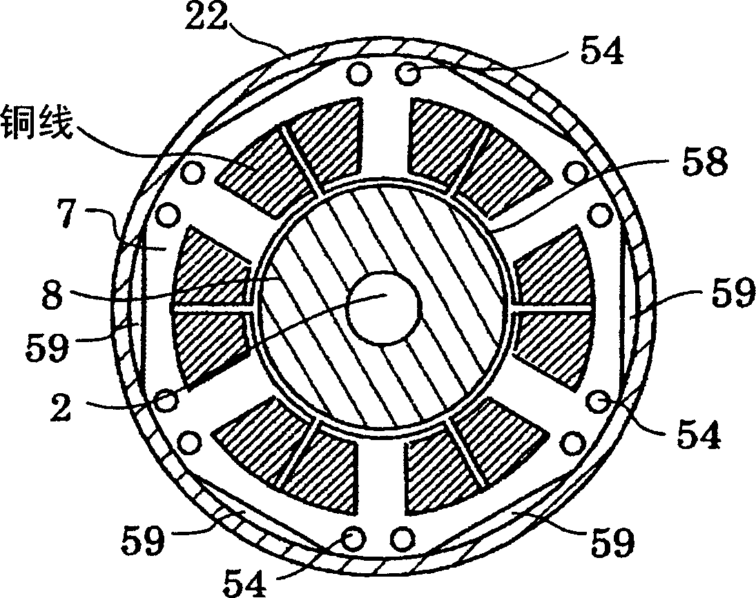
[0021] Embodiments of the present invention are described using drawings. exist figure 1 A vertical cross-sectional view of the rotary two-stage compressor 1 of this embodiment is shown in . The compressor 1 has an airtight container 13 composed of a bottom 21 , a cover 12 , and a body 22 . Below the inside of the airtight container 13, a motor 14 having a stator 7 and a rotor 8 is provided. The rotary shaft 2 to which the motor 14 is connected has two eccentric portions 5, and the main bearing 9 is pivotally supported by the sub bearing 19a. Corresponding to the rotary shaft 2, stacked in order from the motor 14: the main bearing 9 having the end plate portion 9a, the high-pressure compression element 20b, the intermediate partition plate 15, the low-pressure compression element 20a, the end plate portion 19b, and the sub-bearing 19a. The container 19 is integrated with connecting elements 36 such as bolts.

[0022] The end plate portion 9 a is fixed by being welded to th...


PUM


Abstract

The invention provides a rotary two-stage compressor. There are: a motor with a stator and a rotor with an iron core part and copper wires in a closed container; and a rotating shaft with two eccentric parts driven by the motor; A chamber, a rotary compression element having a low-pressure compression element and a high-pressure compression element having rollers orbiting by the eccentric rotation of the eccentric portion; and a compression chamber of the above-mentioned low-pressure compression element and a compression chamber of the high-pressure compression element In the rotary two-stage compressor with an intermediate passage separated by the internal space of the above-mentioned airtight container connected, the above-mentioned stator has a notch passage in the outer peripheral part and an air hole in the above-mentioned iron core part, and the passage cross-sectional area of ​​the space cross-sectional area of ​​the above-mentioned motor is a Cross-sectional area A with respect to the inside of the airtight container, (a/A) is 0.09 or more. Thereby, the oil consumption rate of the rotary type 2-stage compressor whose internal pressure is high pressure in the closed container is reduced.

Description

technical field [0001] The present invention relates to a rotary compressor used in an air conditioner having a refrigeration cycle. Background technique [0002] Conventionally, as a rotary type two-stage compressor used in a refrigeration cycle, for example, what is disclosed in JP-A-60-128990 (hereinafter referred to as Patent Document 1) is common. This prior art compressor has a motor composed of a stator and a rotor on the inside of the airtight container. The rotating shaft connected to the motor has two eccentric parts. As a compression mechanism corresponding to these eccentric portions, a high-pressure compression element and a low-pressure compression element are provided in the airtight container in order from the motor side. [0003] The eccentric rotation of each compression element by the eccentric portion of the rotating shaft causes the rotor to perform orbital motion. These eccentric parts have a phase difference of 180°, and the phase difference of the ...

Claims


Application Information

Patent Timeline
IPC IPC(8): F04C23/00F04C18/356
Inventor 久保田淳渡部一孝金子正人大沼敦井崎宏田所哲也
Owner HITACHI JOHNSON CONTROLS AIR CONDITIONING INC
Why Eureka
Try Eureka