Intelligent cyclic regeneration equipment for cutting fluid

A technology of cyclic regeneration and cutting fluid, applied in the direction of lubricating composition, etc., can solve the problems of increasing the cleaning time of dirty fluid, generating odor, corrosion, etc., to increase the filtering effect and service life, easy to use and replace, and reduce the cost of use. Effect

Active Publication Date: 2014-06-18
中科循美(广东)智能科技有限公司
View PDF2 Cites 22 Cited by
  • Summary
  • Abstract
  • Description
  • Claims
  • Application Information

AI Technical Summary

Problems solved by technology

[0006] 1. Anaerobic bacteria can reduce sulfate, thiosulfate, sulfite, etc., and release mercaptan and hydrogen sulfide gas, resulting in stench, damaging the ecological environment, and affecting human health
[0007] 2. The metabolism of bacteria will produce some acidic substances, which will corrode the machine tools and workpieces, and destroy the stability of the emulsion, greatly reducing the lubrication performance of the cutting fluid
[0008] 3. Bacteria destroy the oily additives and extreme pressure additives in the cutting fluid, which increases the friction force during processing, resulting in increased heat generation, which eventually leads to poor processing surfaces and shortened tool life.
[0010] In summary, the deterioration of cutting fluid not only causes many adverse consequences to metal cutting, but also causes waste of cutting fluid and damage to the ecological environment.
In addition, due to the bad influence of the deteriorated cutting fluid, the machine tool equipment will increase the maintenance cost of the equipment and increase the time for the staff to clean up the dirty fluid, which will affect the work efficiency

Method used


Image

  • Intelligent cyclic regeneration equipment for cutting fluid
  • Intelligent cyclic regeneration equipment for cutting fluid
  • Intelligent cyclic regeneration equipment for cutting fluid

Examples


Embodiment Construction

[0035] The present invention will be further described below in conjunction with specific embodiments and accompanying drawings.

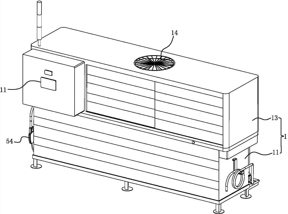
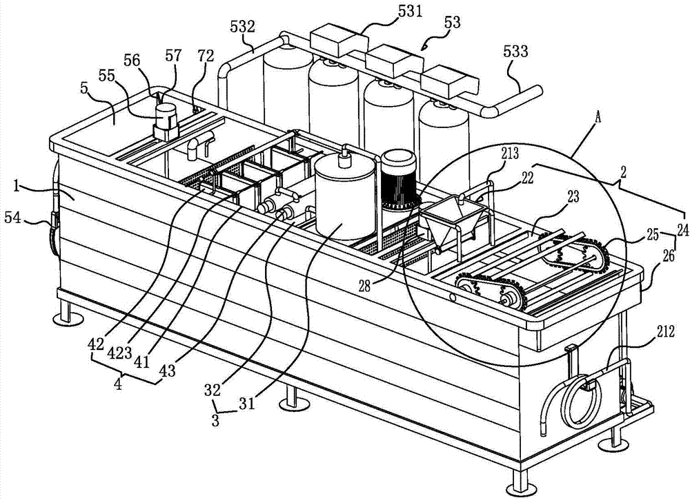
[0036] see Figure 1-7 As shown, it is a cutting fluid intelligent circulation regeneration equipment, which includes: a frame 1 and a first-stage filter device 2 installed on the frame 1, a second-stage filter device 3, a third-stage filter device 4 and a net Liquid tank 5.

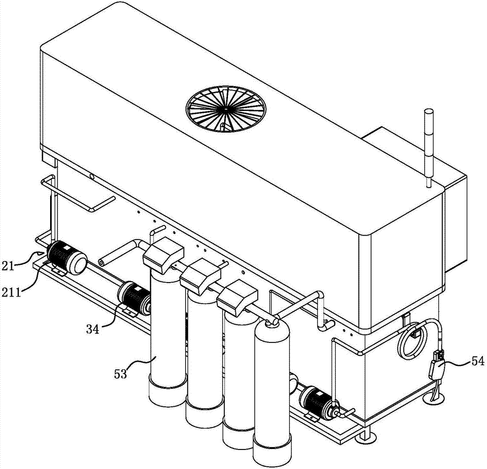
[0037] The first-stage filter device 2 includes: a first suction device 21 installed on the frame 1 and used to suck in external cutting fluid and dirt, and a particle filter 22 for filtering chips and iron powder of the cutting fluid and dirt , a dirty liquid tank 23 for containing liquid and a first agitator 28 arranged in the dirty liquid tank 23, an alum water injection device 27 and a high-efficiency degreasing device 24.

[0038] The first suction device 21 includes: a first centrifugal pump 211 installed on the outside of the frame 1 and a first pipe body 212 and a s...


PUM


Abstract

The invention discloses intelligent cyclic regeneration equipment for cutting fluid. The intelligent cyclic regeneration equipment comprises a rack, a first stage of filter device, a second stage of filter device, a third stage of filter device, and a liquid purifying box, wherein a control system touch screen is arranged on the rack; the first stage of filter device comprises a first suction device, a particulate matter filter, a soiling solution tank, a first agitator, a white alum water injection device and an efficient oil removing device; the second stage of filter device comprises a high-speed centrifugal filter device, a first filter tank and a second suction device; the third stage of filter device comprises a second filter tank, an ultraviolet sterilization device and a bag-type zipper filter device; a concentration monitoring device, a concentrate supplement device and a deionized water supplement device are arranged inside the liquid purifying box; the first stage of filter device, the second stage of filter device, the third stage of filter device and the liquid purifying box are internally provided with deodorization devices. By adopting the intelligent cyclic regeneration equipment, cuttings, iron powder, oil slick pollution, cenobium, floccules and impurities in a soiling solution of the cutting liquid can be effectively removed, new cutting liquid with proper concentration is formed, and the intelligent cyclic regeneration equipment also has sterilization and deodorization functions.

Description

Technical field: [0001] The invention relates to the technical field of cutting fluid treatment equipment, in particular to a cutting fluid intelligent cycle regeneration equipment. Background technique: [0002] With the development of the overall technology of the machinery industry, the cutting speed of machine tools is faster, the cutting load is greater, and the cutting temperature is higher. At the same time, new processes are constantly emerging to adapt to the processing of new materials, which require new high-performance cutting fluids to meet processing requirements. , Therefore, the development of cutting fluid has become a trend. [0003] Cutting fluid coolant is an industrial liquid used in metal cutting and grinding processes to cool and lubricate tools and workpieces. Cutting fluid is made of a variety of super functional additives through scientific compound compatibility At the same time, it has good cooling performance, lubricating performance, anti-rust ...

Claims


Application Information

Patent Timeline
Patent Type & Authority Applications(China)
IPC IPC(8): C10M175/00
Inventor 冯坚
Owner 中科循美(广东)智能科技有限公司
Why Eureka
Try Eureka