
Visual contraposition method of not corresponding basis material

A visual alignment, non-corresponding technology, applied in the direction of instruments, character and pattern recognition, electrical components, etc., can solve problems such as unpredictable alignment point coordinates, alignment features do not correspond, and accurate alignment cannot be performed.

Inactive Publication Date: 2006-07-05
IND TECH RES INST
View PDF0 Cites 4 Cited by
  • Summary
  • Abstract
  • Description
  • Claims
  • Application Information

AI Technical Summary

Problems solved by technology

[0007] (1) When the alignment point of the base material to be aligned is not clear, accurate alignment cannot be performed
[0008] (2) If the alignment features of the substrate to be aligned do not correspond, accurate alignment cannot be perform

Method used

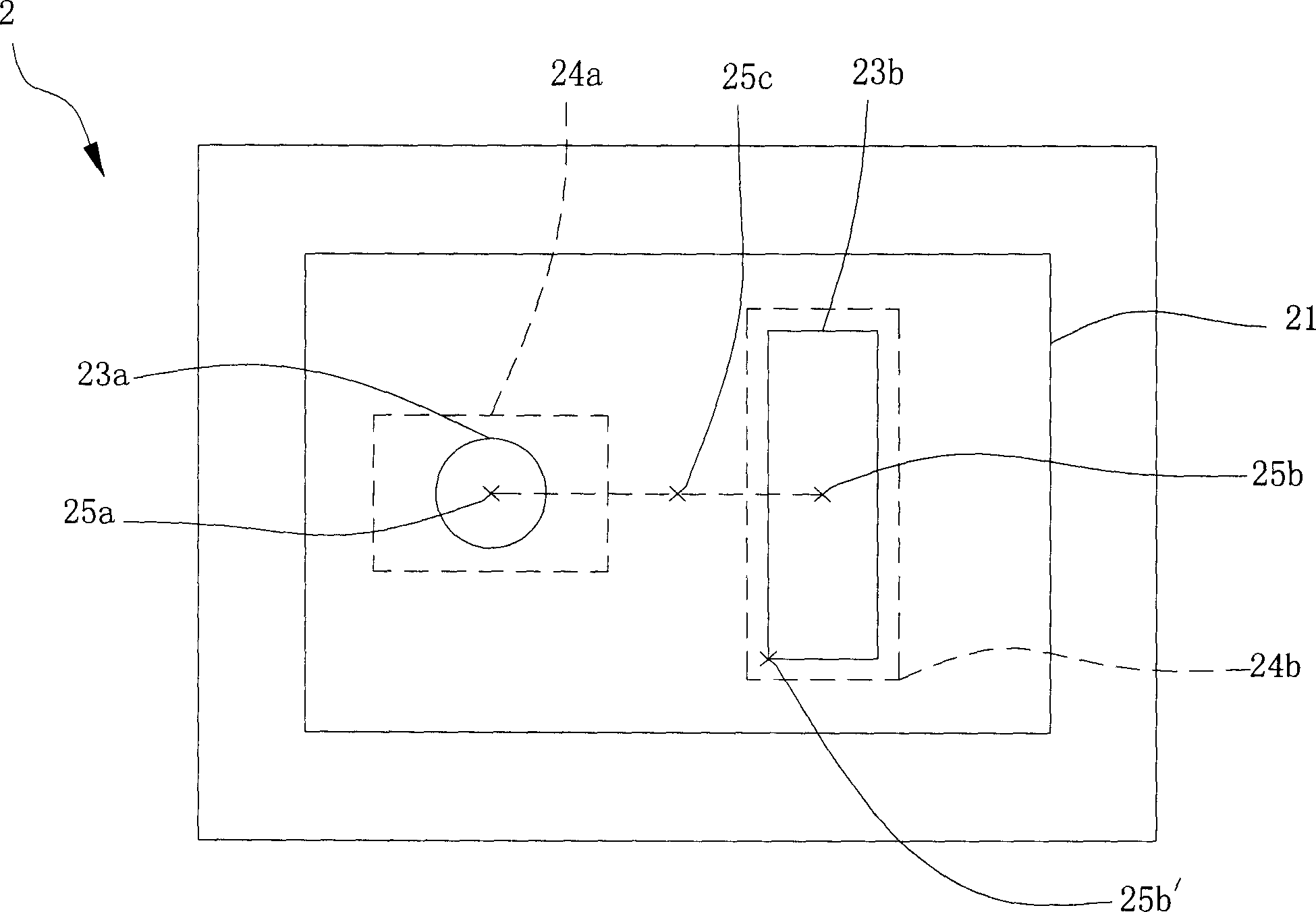
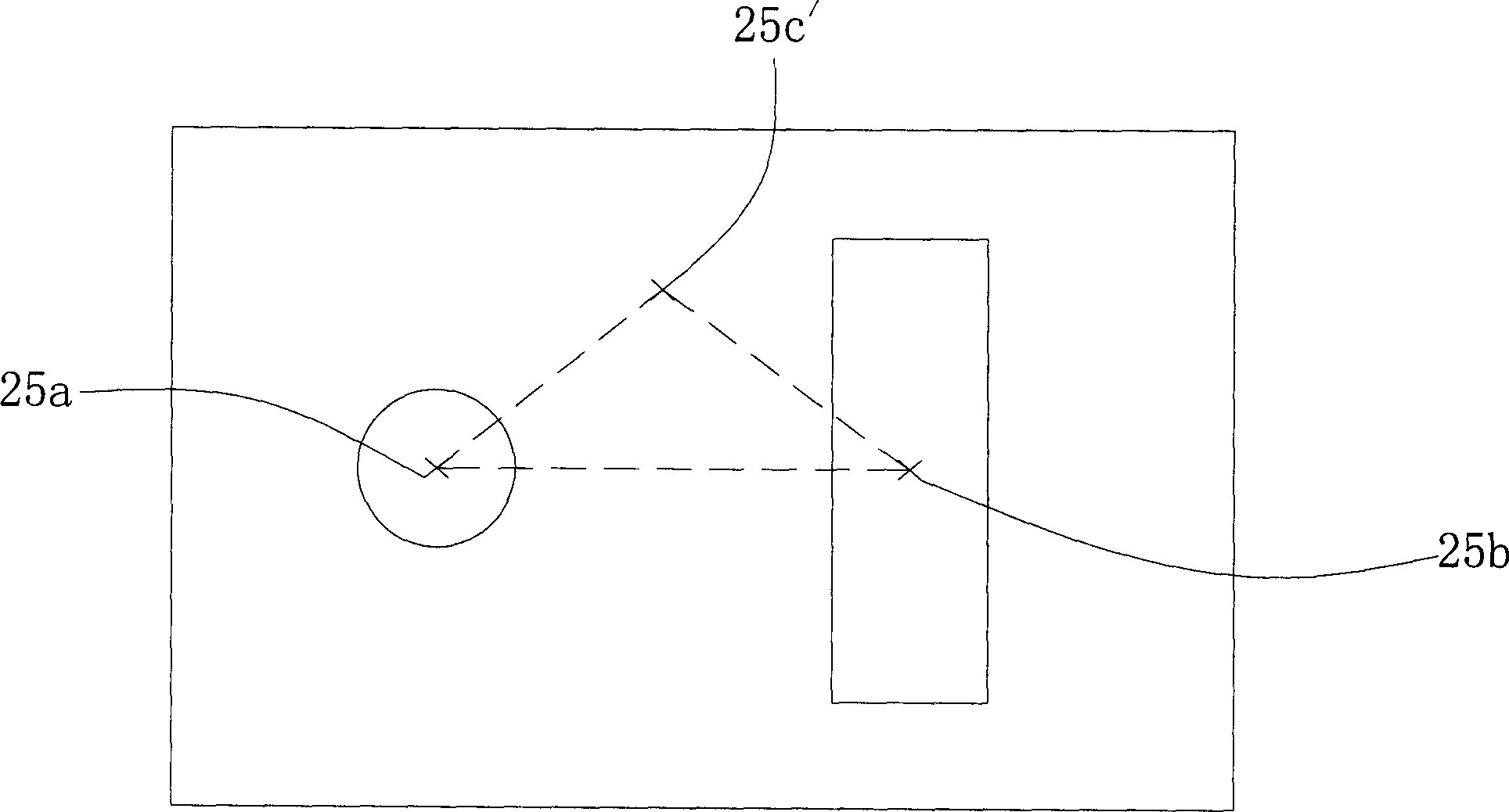

Image

  • Visual contraposition method of not corresponding basis material
  • Visual contraposition method of not corresponding basis material
  • Visual contraposition method of not corresponding basis material

Examples


Embodiment Construction

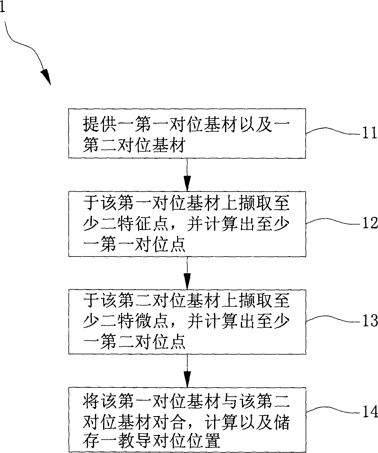
[0043] see figure 1 As shown, this figure is a schematic flow chart of the first preferred embodiment of the visual alignment method for non-corresponding substrates of the present invention. The visual alignment method 1 of the non-corresponding substrate includes the following steps:

[0044] Step 11 - providing a first alignment substrate and a second alignment substrate;

[0045] Step 12 - selecting at least two first feature points on the first alignment substrate and calculating at least one first pair of positional points having a relative positional relationship with the at least two first feature points;

[0046] Step 13 - selecting at least two second feature points on the second alignment substrate and calculating at least one second alignment point having a relative positional relationship with the at least two second feature points; and

[0047] Step 14 Select a corresponding position and teach the first alignment substrate to align with the second alignment sub...


PUM


Abstract

The invention relates to a non-corresponding substrate visual aligning method, comprising the steps of: providing a first aligning substrate and a second aligning substrate; selecting at least two first characteristic points on the first aligning substrate and calculating at least a first aligning point relative to the first characteristic points; selecting at least two second characteristic points on the second substrate and calculating at least a second aligning point relative to the second characteristic points; using a teaching frame only able to drag position but unable to change size, selecting a corresponding position and teaching the first aligning substrate to align with the second one; in the aligning state, calculating a relative position to the first and second aligning points.

Description

technical field [0001] The invention relates to a visual alignment method for non-corresponding substrates, in particular to a visual alignment method for non-corresponding substrates which utilizes visual technology to process the asymmetry of the characteristic pattern of the corresponding point of the alignment substrate. Background technique [0002] Since machine vision technology uses program algorithms to process high-resolution images, it can meet the requirements of high-precision positioning or alignment of precision machinery equipment, and has now widely become a key module of precision machinery equipment. [0003] With the miniaturization of electronic components, the requirements for positioning accuracy are gradually increasing. Under the circumstances that traditional machinery cannot overcome, the use of machine vision technology to solve related problems in the industry has gradually become the mainstream. In this field, there are about the following Techn...

Claims


Application Information

Patent Timeline
IPC IPC(8): G06K9/32G06K9/46H05K13/08H01L21/00
Inventor 蔡雅惠刘俊贤林宏毅黄清国陈维昱
Owner IND TECH RES INST
Learn More