Joint terminal

A technology of terminal blocks and electric wires, applied in the direction of connection, conductive connection, contact manufacturing, etc., can solve problems such as troublesome installation and complexity, and achieve the effect of good easy contact and reliable support and fixation

Inactive Publication Date: 2006-07-26
SIEMENS AG
View PDF1 Cites 7 Cited by
  • Summary
  • Abstract
  • Description
  • Claims
  • Application Information

AI Technical Summary

Problems solved by technology

However, the screwless terminal disclosed therein has a complex structure which makes it very cumbersome to assemble the individual components of the terminal

Method used


Image

  • Joint terminal
  • Joint terminal
  • Joint terminal

Examples


Embodiment Construction

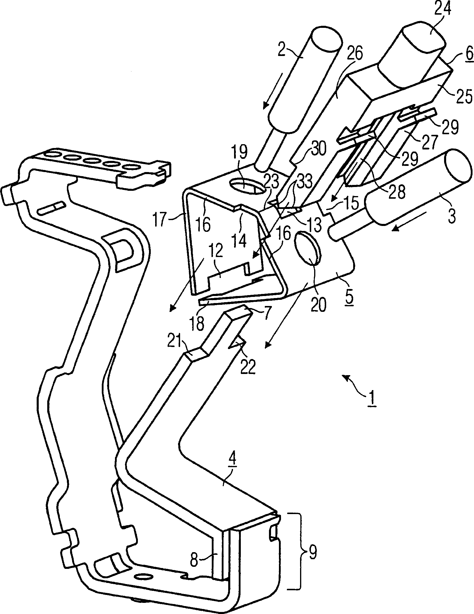
[0024] exist figure 1 shows a bolt-free elastic terminal 1 in a three-dimensional exploded view. In this case, the connection terminal 1 or plug terminal is used to connect a first partially stripped electrical conductor 2 and a partially stripped second electrical conductor 3 . The assembly of the connection terminal 1 has a support element 4 , a spring element 5 and an actuating element 6 , which can be assembled to form an assembly by mutual plug-in connections along the direction arrows. The component can thus be temporarily stored as a functionally reliable pre-assembled structural unit until further use.

[0025] Support elements 4 in accordance with figure 1 It is part of a bimetal support, which can be a one-piece, that is to say continuous or two-piece structure. In a two-part construction, the support element 4 has, at its fastening end 8 opposite the free end 7 , a connection point 9 which can be designed, for example, as a welding point.

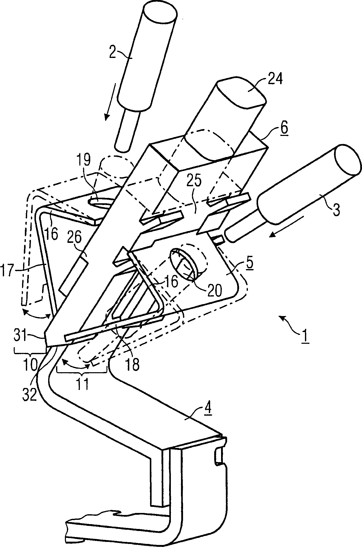
[0026] exist figure...


PUM


Abstract

For illustrating a connection terminal (1) with a compact and easily-assembled structure, a supporting element (4) is adopted to fix an elastic element (5); meanwhile, the elastic element (5) is used to fix at least one electrical conductor (2, 3) and a control element (6) acted on the elastic element (5) is used to release the electrical conductor. In the invention, splicing connection relations are formed between the supporting element (4) and the elastic element (5), and between the control element (6) and the elastic element.

Description

technical field [0001] The invention relates to a terminal for connecting an electrical conductor, which has a support element for fixing a spring element, wherein at least one electrical conductor can be fixed by means of the spring element and by means of an action on the spring element The operating element can release the electrical lead. Background technique [0002] Such a terminal is additionally used for the conductive connection of one or more conductors to a current path of an electrical device or to other conductors. [0003] A terminal of this type is known from DE 37 43 410 A1. However, the screwless terminal disclosed therein has a complex construction which makes it very complicated to assemble the individual components of the terminal. Contents of the invention [0004] The technical problem to be solved by the present invention is to provide a connection terminal of the type mentioned in the introduction which is compact in structure and easy to install....

Claims


Application Information

Patent Timeline
IPC IPC(8): H01R4/28H01R43/16
CPCH01R4/4836H01R4/48365
Inventor 冈瑟·埃克特斯蒂芬·霍赫克里斯托弗·韦伯
Owner SIEMENS AG
Why Eureka
Try Eureka