Keyboard keys

A button and keyboard technology, which is applied to the structural field of a single button on an ATM operating keyboard, can solve problems such as blurred and unrecognizable signs, and increase the overall cost of equipment use and maintenance, and achieve the effects of reducing manufacturing and maintenance costs and improving wear resistance

Active Publication Date: 2006-08-02
SHENZHEN ZHENGTONG ELECTRONICS
View PDF0 Cites 51 Cited by
  • Summary
  • Abstract
  • Description
  • Claims
  • Application Information

AI Technical Summary

Problems solved by technology

On the other hand, after the keyboard has been used for a long time, the logos tend to become blurred or even unrecognizable due to wear and tear, and once individual logos need to be replaced, the entire keycap of the key needs to be replaced, which also increases the overall maintenance of the equipment. cost
[000

Method used


Image

  • Keyboard keys
  • Keyboard keys
  • Keyboard keys

Examples


Embodiment Construction

[0025] Describe in detail below in conjunction with the preferred embodiment of the present invention shown in accompanying drawing

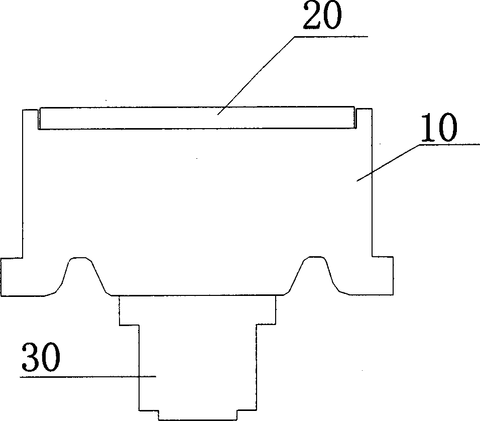
[0026] Keyboard keys of the present invention, such as figure 1 As shown, it includes a key contact 30, a metal keycap 10 connected to the key contact 30, and a panel 20 positioned on the metal keycap 10; Grooving. The actual connection between the bottom of the metal keycap 10 and the key contacts 30 is located in the groove at the bottom of the metal keycap 10 . In order to enhance the reliability of the button operation, the user's button action is evenly transmitted to the button contact 30 through the keycap 10, and then the button circuit is triggered by the contact 30, and the button contact 30 is specially designed to be smaller than the metal key. The bottom of the cap 10 is embedded in the concave groove at the bottom of the metal key cap 10 .

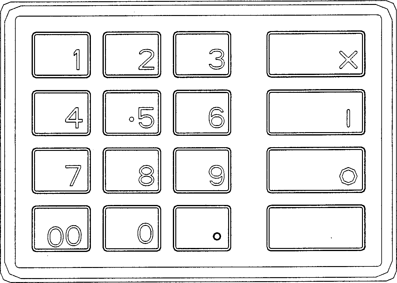
[0027] figure 2 The key distribution of the main body of the keyboard is given, the le...


PUM


Abstract

This invention is a kind of keyboard keystroke which concludes keystroke contact-head, metal keycap connected with keystroke contactor, board above the metal keycap. There are notch using for embedding the said board on the said metal keycap. The board is made of metal. Its surface

Description

technical field [0001] The invention relates to financial equipment, in particular to an ATM (automatic teller machine) operating keyboard, in particular to the structure of a single button on the ATM operating keyboard. Background technique [0002] The structure of a single key on the existing ATM operating keyboard mostly adopts an integrated metal key cap, and the key is identified by silk screen printing, pasting or embossing the key symbol on the key cap. The main part of the ATM operation keyboard is usually arranged with 4*4 keys, the 4*3 on the left is the number part, and the 4*1 on the right is the command part. The number part, according to the sequence from left to right, from top to bottom is: [1, 2, 3, 4, 5, 6, 7, 8, 9, 00, 0, .], in order to facilitate the operation of the blind, generally On the [5] key, set the button arrangement position indicator for the blind. The order of the order from top to bottom is: [Cancel, Change, Enter, Reserve], where the res...

Claims


Application Information

Patent Timeline
IPC IPC(8): H01H13/14G06F3/02
Inventor 谢立民黄洪
Owner SHENZHEN ZHENGTONG ELECTRONICS
Why Eureka
Try Eureka