
Lens having at least one lens centration mark and methods of making and using same

A coaxiality and lens technology, applied in the direction of lenses, manufacturing tools, glasses/goggles, etc., can solve the problems of uneven shrinkage, misalignment of mechanical axes, etc., and achieve the effect of accurate measurement of coaxiality

Inactive Publication Date: 2006-08-16
3M INNOVATIVE PROPERTIES CO
View PDF1 Cites 7 Cited by
  • Summary
  • Abstract
  • Description
  • Claims
  • Application Information

AI Technical Summary

Problems solved by technology

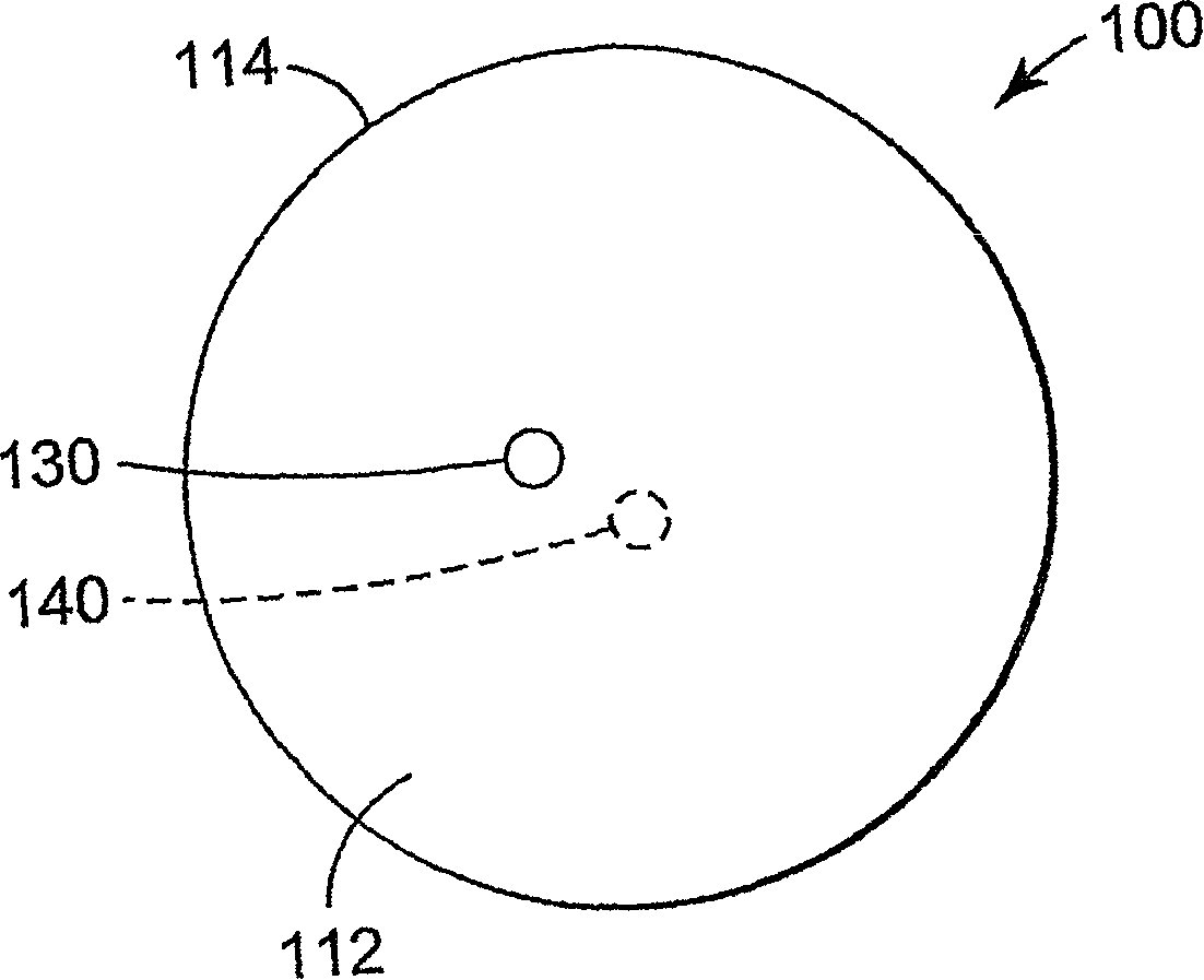
For example, the two mold pins that make up the injection mold may not be strictly aligned with each other such that the optical axis of one or both lens surfaces does not coincide with the mechanical axis of the lens
Also, curable materials used in injection molding processes may shrink unevenly during curing

Method used


Image

  • Lens having at least one lens centration mark and methods of making and using same
  • Lens having at least one lens centration mark and methods of making and using same
  • Lens having at least one lens centration mark and methods of making and using same

Examples


Embodiment Construction

[0032] In the following detailed description of exemplary embodiments, reference is made to the accompanying drawings which form a part hereof, and in which are shown by way of illustrations specific embodiments in which the invention may be practiced. It is to be understood that other embodiments may be utilized and structural changes may be made without departing from the scope of the present invention.

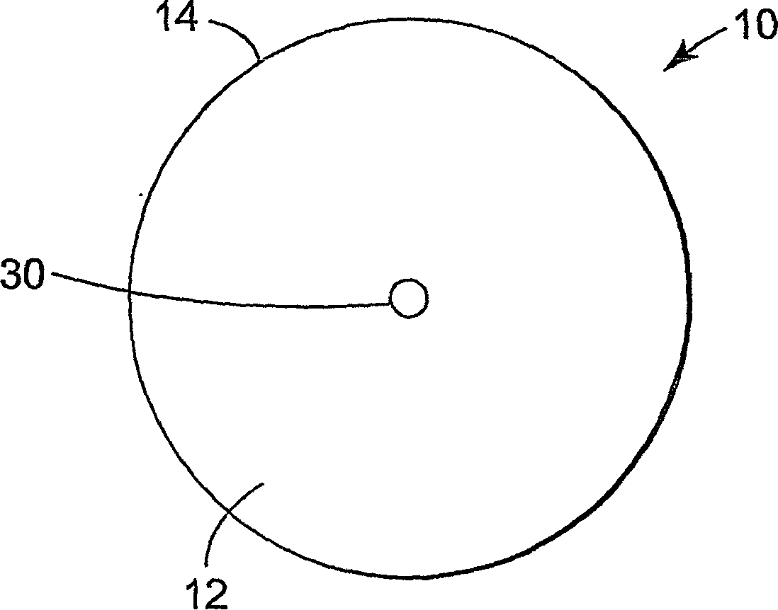
[0033] Generally, the lenses of the present invention include at least one indicia of lens coaxiality on a major surface of the lens.

[0034] As used herein, the term "aspherical lens" refers to a lens in which at least one surface of the lens is shaped as an aspheric surface that rotates about an axis of revolution.

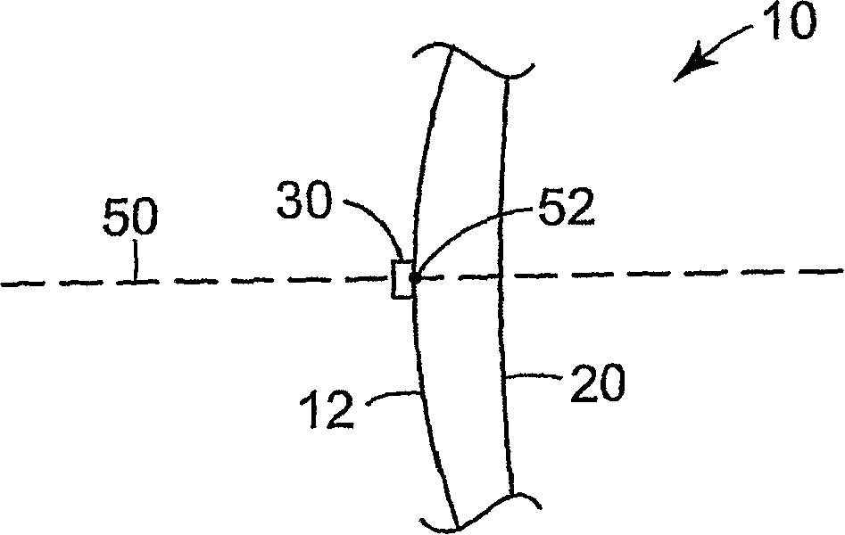
[0035] As used herein, the term "vertex" refers to the point on a surface of revolution where the axis of revolution intersects the surface of revolution.

[0036] As used herein, the term "optical axis" refers to the axis passing through the apex of a lens...


PUM


Abstract

A lens having at least one lens centration mark formed on a major surface of the lens is disclosed. The lens centration mark may be located at the intersection of a first axis and the major surface, where the major surface is symmetrical about the first axis such that the first axis is an axis of revolution of the surface. A method of making a lens having such lens centration mark, as well as a method for measuring the centration of a lens surface utilizing the lens centration mark, are also disclosed.

Description

technical field [0001] The present invention relates generally to the field of lenses, and in particular, to lenses having at least one lens coaxiality marker and methods of making the same. Background technique [0002] Optical components often require testing to determine optical and mechanical properties. For example, it is often necessary to test a lens to determine the coaxiality of one or both lens surfaces. [0003] Lens designers are interested in the study of aspheric surfaces to help control the various types of optical aberrations that may occur in spherical lenses. In general, an aspheric surface is understood to be a surface of revolution of a shape formed by rotating a non-circular curve about an axis of revolution. The swivel surface is thus rotationally symmetrical about the swivel axis. Each aspheric surface belonging to a surface of revolution includes a vertex, which is defined as the point on the surface where the surface intersects the axis of revolut...

Claims


Application Information

Patent Timeline
IPC IPC(8): B24B13/005B29D11/00G02C7/02
CPCB24B13/0055G02C7/021
Inventor 爱德华·L·琼斯
Owner 3M INNOVATIVE PROPERTIES CO
Learn More