Cooling and support systems for furnace roofs

A furnace roof and furnace technology, applied in the direction of furnace cooling device, furnace cooling, furnace crown/roof, etc., can solve the problems that refractory bricks cannot be replaced from above, shorten the service life, and affect the removal of dust and debris, so as to shorten the time period and cost, the effect of simplifying the time period and cost

Active Publication Date: 2006-08-30
HATCH LTD
View PDF1 Cites 5 Cited by
  • Summary
  • Abstract
  • Description
  • Claims
  • Application Information

AI Technical Summary

Problems solved by technology

[0005] While the Gates patented system offers some advantages over conventional hanger systems, the grid of transverse and longitudinal tubular members can interfere with the ability to remove dust and debris from the furnace roof
This cleaning is necessary to maximize the life of the furnace, as dust is trapped and, if not removed, will cause the bricks to heat up, thus reducing their life
In addition, the refractory bricks in the vaults of the Gates furnaces do not appear to be replaceable from above but must be replaced from inside the furnace, requiring a furnace cold shutdown and therefore loss of production
[0006] Additionally, it is not desirable to support the roof on the walls as disclosed in the Gates patent, since the roof would then have to be removed or otherwise supported to replace the wall tiles, which generally would have to be done more often than the roof repairs

Method used


Image

  • Cooling and support systems for furnace roofs
  • Cooling and support systems for furnace roofs
  • Cooling and support systems for furnace roofs

Examples


Embodiment Construction

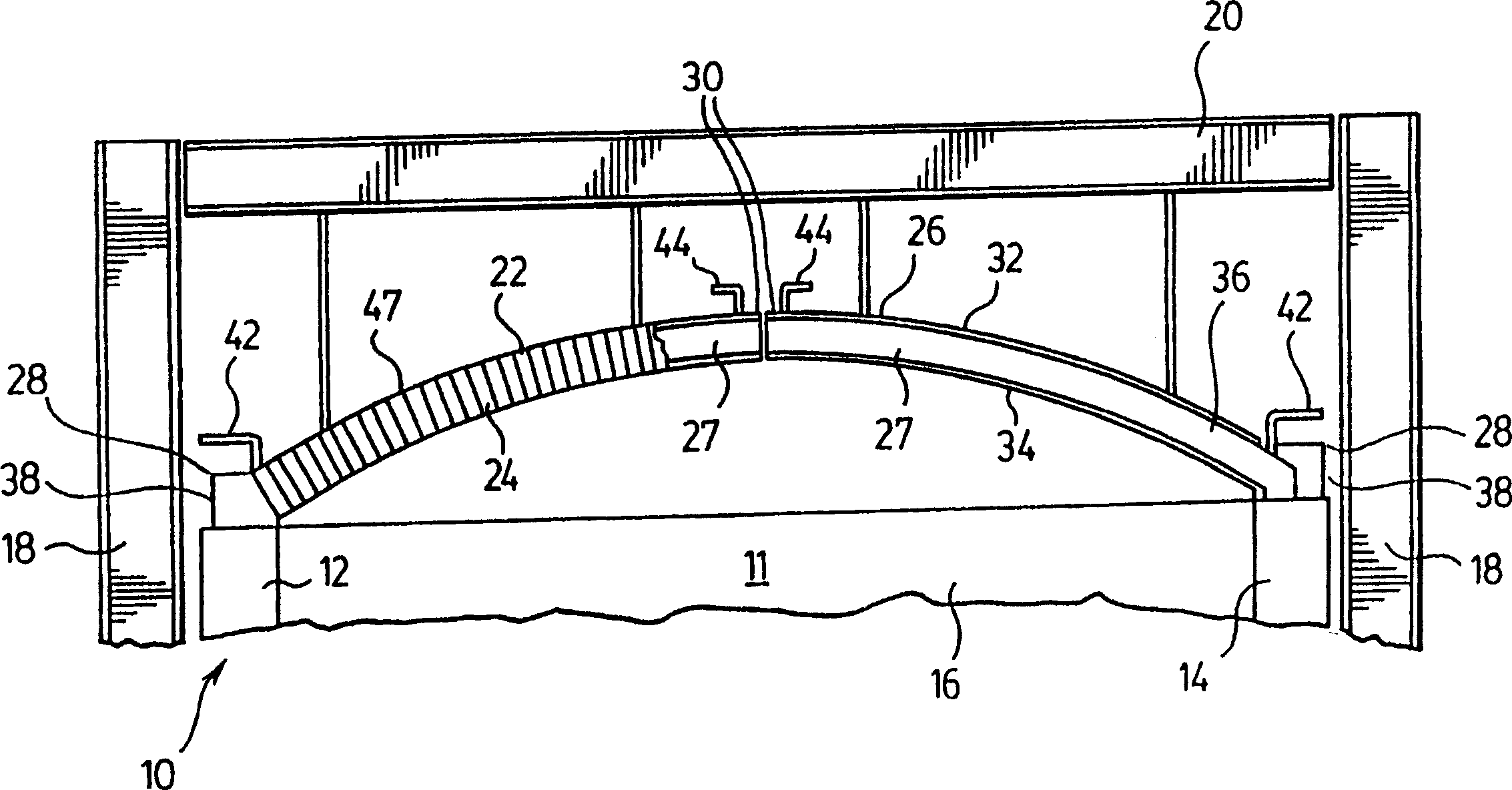
[0017] figure 1 A portion of a furnace 10 is schematically shown, which is rectangular in shape and has four vertically extending walls surrounding an interior space 11, preferably constructed of a refractory material. Parts of side walls 12, 14 and end wall 16 are shown in figure 1 middle. Although the preferred embodiment of the invention is described in connection with a rectangular furnace, it will be appreciated that the principles practiced in the invention can be applied to furnaces of various shapes, such as circular furnaces having generally cylindrical side walls.

[0018] Supporting the side walls 12 and 14 of the furnace 10 are vertical beams commonly referred to as "pillars". These columns are arranged in pairs along opposite sides of the furnace 10 . Although figure 1 Only one pair of struts 18 is shown in , but it will be appreciated that there are preferably a plurality of such pairs of struts spaced apart along the length of the side walls 12 and 14 . Ext...


PUM


Abstract

A system for supporting and cooling a furnace roof comprised of refractory bricks comprises a plurality of roof support members extending across the furnace and being supported from above the furnace roof. The support members are provided with internal channels for circulation of a cooling fluid, and are provided with side surfaces adapted to support rows or refractory bricks between adjacent roof support members. The system eliminates the need to suspend individual bricks from above the roof, and provides simultaneous support and cooling of the roof structure.

Description

field of invention [0001] The present invention relates to a system for suspending and cooling the roof of a refractory furnace. Background of the invention [0002] High temperature furnaces have a roof structure consisting of refractory bricks. The bricks are supported by hanger beams through metal hangers. Many systems are known where the bricks interlock with each other so that the number of hangers is reduced. However, most of these hangers typically protrude from the furnace roof, making it difficult to keep the furnace roof free of dust and debris, thereby impeding heat removal from the furnace roof refractory and thus reducing its useful life. [0003] Typically, furnace roof suspension systems do not include means for cooling the refractory bricks that make up the roof. The system disclosed in US Patent No. 1,404,845 (Gates), issued January 31, 1922, is an exception. This patent discloses a furnace "arch" having a grid of interconnected tubular members through w...

Claims


Application Information

Patent Timeline
Patent Type & Authority Applications(China)
IPC IPC(8): F27D1/02F27D1/12F23M5/04F23M5/06F27D1/04F27D9/00
CPCF23M5/04F23M5/06F27D1/021F27D9/00F27D1/04
Inventor K·M·唐纳森B·O·沃斯芒德K·T·哈钦森N·W·沃尔曼B·T·埃默里
Owner HATCH LTD
Why Eureka
Try Eureka