Flow controller and its regulation method
A flow control device and flow control technology, applied in the direction of measuring device, fluid pressure control, non-electric variable control, etc., can solve the problem of different real flow
- Summary
- Abstract
- Description
- Claims
- Application Information
AI Technical Summary
Problems solved by technology
Method used
Image

Examples
no. 1 Embodiment
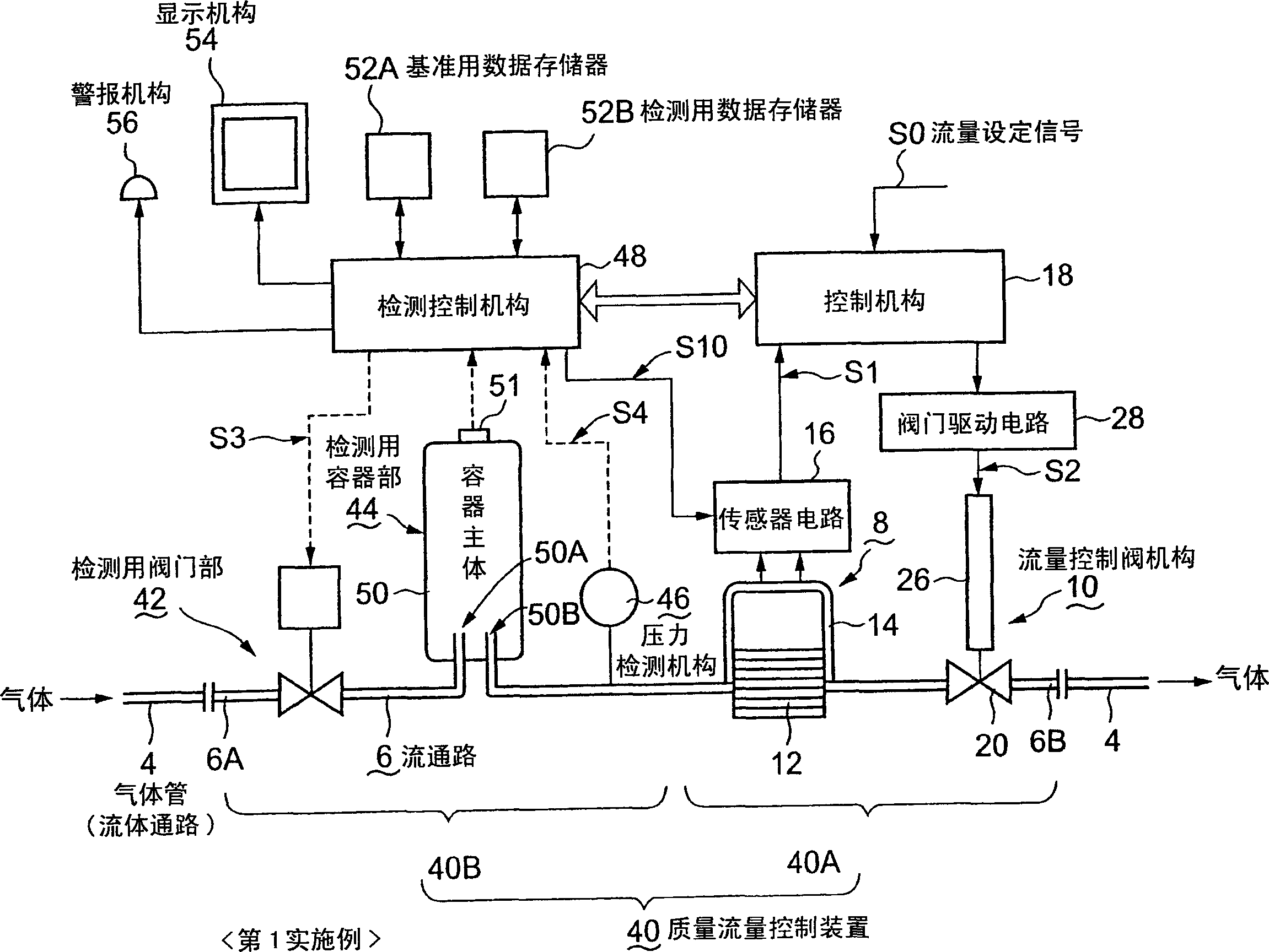
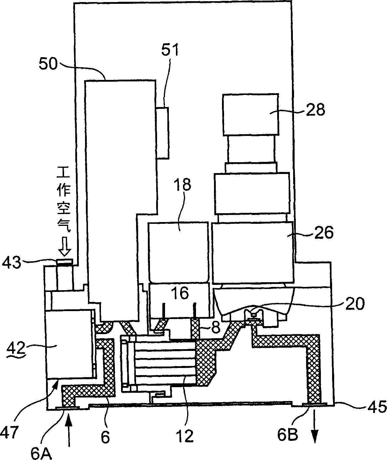
[0075] figure 1 It is a block diagram showing the first embodiment of the related mass flow control device of the present invention. figure 2 It is an arrangement diagram showing the actual arrangement state of each component in the first embodiment. Also, give Figure 17 as well as Figure 18 Components that are the same as those shown in , are denoted by the same symbols, and descriptions thereof are omitted.
[0076] As shown in the figure, the mass flow control device 40 is interposed in the middle of a fluid channel through which fluid such as liquid or gas flows, such as the gas pipe 4, and controls its mass flow rate (hereinafter also referred to as "flow rate"). In addition, the inside of the semiconductor manufacturing apparatus connected to one end of the gas tube 4 is evacuated, for example. This mass flow control device 40 has a mass flow control main body 40A and a detection main body 40B that detects a mass flow rate, which is a feature of the present invent...
no. 2 Embodiment
[0138] Next, a second embodiment of the related mass flow control device of the present invention will be described.
[0139] In this second embodiment, the function of enabling high-accuracy zero-point adjustment is provided, and at the same time, the size and compactness of the device itself can be realized.
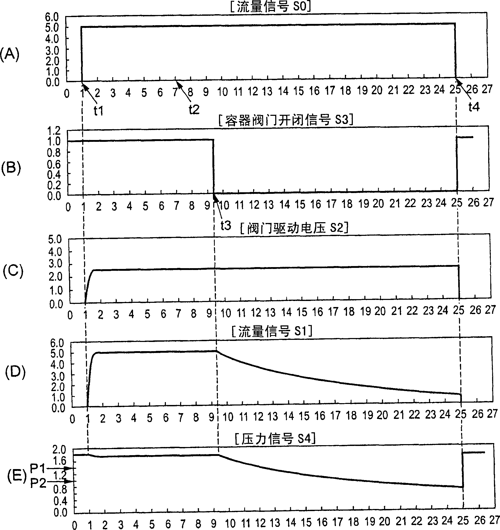
[0140] In this kind of mass flow control device, although the zero point of the flow detection is only slightly changed due to time-dependent changes, the deviation is unavoidable. Therefore, the zero point adjustment is carried out regularly or irregularly. However, in order to improve the accuracy of the zero point adjustment, it is best It is best to completely stop the flow of fluid (including gas and liquid) inside the device. In this case, even if the flow control valve 20 using a diaphragm is in the valve-closed state, it is difficult to completely cut off the flow of the fluid due to its characteristics. Although it is only a little bit, an extremely small amou...
no. 3 Embodiment
[0163] Figure 13 It is a block diagram showing a third embodiment of the related mass flow control device of the present invention. The mass flow control device 401 of the third embodiment differs from the mass flow control device 40 of the first embodiment in that the detection execution unit 401B is located downstream of the mass flow control unit 401A in the flow path 6 . In addition, the detection execution part 401B of the mass flow control device 401 of the third embodiment is different from the mass flow control of the first embodiment in that the detection valve part 42 is provided downstream of the detection container part 44 and the pressure detection mechanism 46. The detection execution unit 40B of the device 40 is different. Other aspects of the configuration of the mass flow control device 401 of the third embodiment are the same as those of the mass flow control device 40 of the first embodiment.
[0164] In the third embodiment, first, the mass flow control ...
PUM
 Abstract
Description
Claims
Application Information
 - R&D
- Intellectual Property
- Life Sciences
- Materials
- Tech Scout
- Unparalleled Data Quality
- Higher Quality Content
- 60% Fewer Hallucinations
Browse by: Latest US Patents, China's latest patents, Technical Efficacy Thesaurus, Application Domain, Technology Topic, Popular Technical Reports.
© 2025 PatSnap. All rights reserved.Legal|Privacy policy|Modern Slavery Act Transparency Statement|Sitemap|About US| Contact US: help@patsnap.com