Supercharge Your Innovation With Domain-Expert AI Agents!

Road-marking system

A road sign and roadway technology, applied in the field of road sign systems to achieve the effect of improving traffic safety

Inactive Publication Date: 2006-10-11
KONINKLIJKE PHILIPS ELECTRONICS NV
View PDF0 Cites 7 Cited by
  • Summary
  • Abstract
  • Description
  • Claims
  • Application Information

AI Technical Summary

Problems solved by technology

[0004] A disadvantage of known road marking systems is that they cannot be used to dynamically influence the distance between vehicles traveling on the road

Method used


Image

  • Road-marking system
  • Road-marking system
  • Road-marking system

Examples


Embodiment Construction

[0027] The drawings are by way of illustration only and are not drawn to scale. Particularly for clarity, some dimensions are strongly exaggerated. In the illustrations, like reference numerals refer to like parts wherever possible.

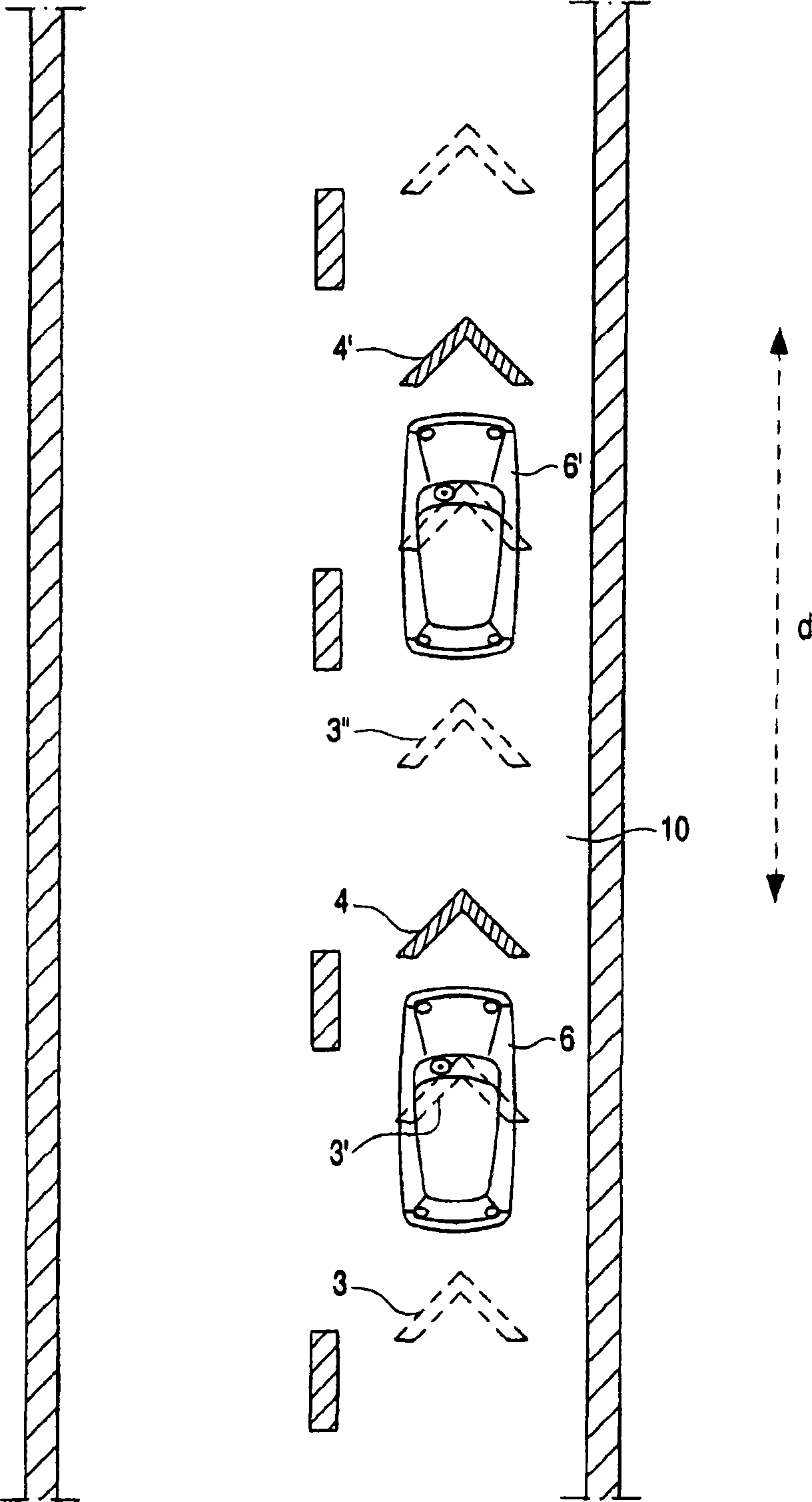
[0028] figure 1 A plan view of a road marking system for influencing the distance between vehicles 6, 6', . . . traveling on a roadway 10 is schematically shown. The road marking system comprises a plurality of road marking units 3; 3', 3", ...; 4, 4', .... The road marking units 3; 3', 3", ...; 4 , 4', ... are equipped with lighting means for emitting or reflecting light towards the driver of the vehicle 6, 6', .... In operation, a group of road marking units 4, 4', ... is active, while the remaining road marking units 3; 3', 3", ... are inactive. The active road marking units in the group 4, 4', ... the distance between (the above distance in figure 1 marked with d in ) represents the desired distance between the vehicles 6, 6', ....

[0...


PUM


Abstract

The road-marking system for influencing the distance between vehicles (6, 6',...) traveling over a roadway (10) comprises: a plurality of road-marking units (3; 3', 3'', ...; 4, 4', ...), the road-marking units being provided with light means for emitting or reflecting light in the direction of a driver of the vehicle (6, 6', ...). In operation, a set of the road-marking units (4, 4', ...) is in an active state, while the remainder of the road-marking units (3; 3', 3'', ...) is in an inactive state. The distance between the active road-marking units (4, 4', ...) in the set is indicative of the desired distance between the vehicles (6, 6', ...). Preferably, the light emitted or reflected by the set of active road-marking units (4, 4', ...) is tuned in response to conditions during the day or during the night.

Description

technical field [0001] The invention relates to a road marking system for influencing the distance between vehicles traveling on a roadway. Background technique [0002] In traffic control systems, road marking systems are used to mark traffic routes for vehicles such as passenger cars and other road users. One of the ways transportation planners are trying to reduce traffic congestion is the so-called "tidal flow system." In such road marking systems, the direction of travel on a multi-lane road is changed for one or more lanes according to the prevailing direction of traffic flow. According to another alternative embodiment, the number of lanes available for traffic moving in a certain direction is increased or decreased depending on the traffic volume. [0003] Road marking systems for influencing the distance between vehicles traveling on a roadway are known in the art. One way of influencing the distance between vehicles traveling along a roadway is to apply so-calle...

Claims


Application Information

Patent Timeline
IPC IPC(8): E01F9/00E01F9/06G08G1/16G02F1/167
CPCE01F9/065E01F9/005G02F1/167E01F9/30E01F9/559
Inventor L·L·D·范德波尔
Owner KONINKLIJKE PHILIPS ELECTRONICS NV
Features
  • R&D
  • Intellectual Property
  • Life Sciences
  • Materials
  • Tech Scout
  • Unparalleled Data Quality
  • Higher Quality Content
  • 60% Fewer Hallucinations
Learn More