

Optical network configuration for transmitting optical signals
A network configuration, optical network technology, applied in transmission system, electromagnetic network arrangement, electromagnetic network combination and other directions, can solve problems such as reducing bandwidth
- Summary
- Abstract
- Description
- Claims
- Application Information
AI Technical Summary
Problems solved by technology
Method used
Image

Examples
Embodiment Construction
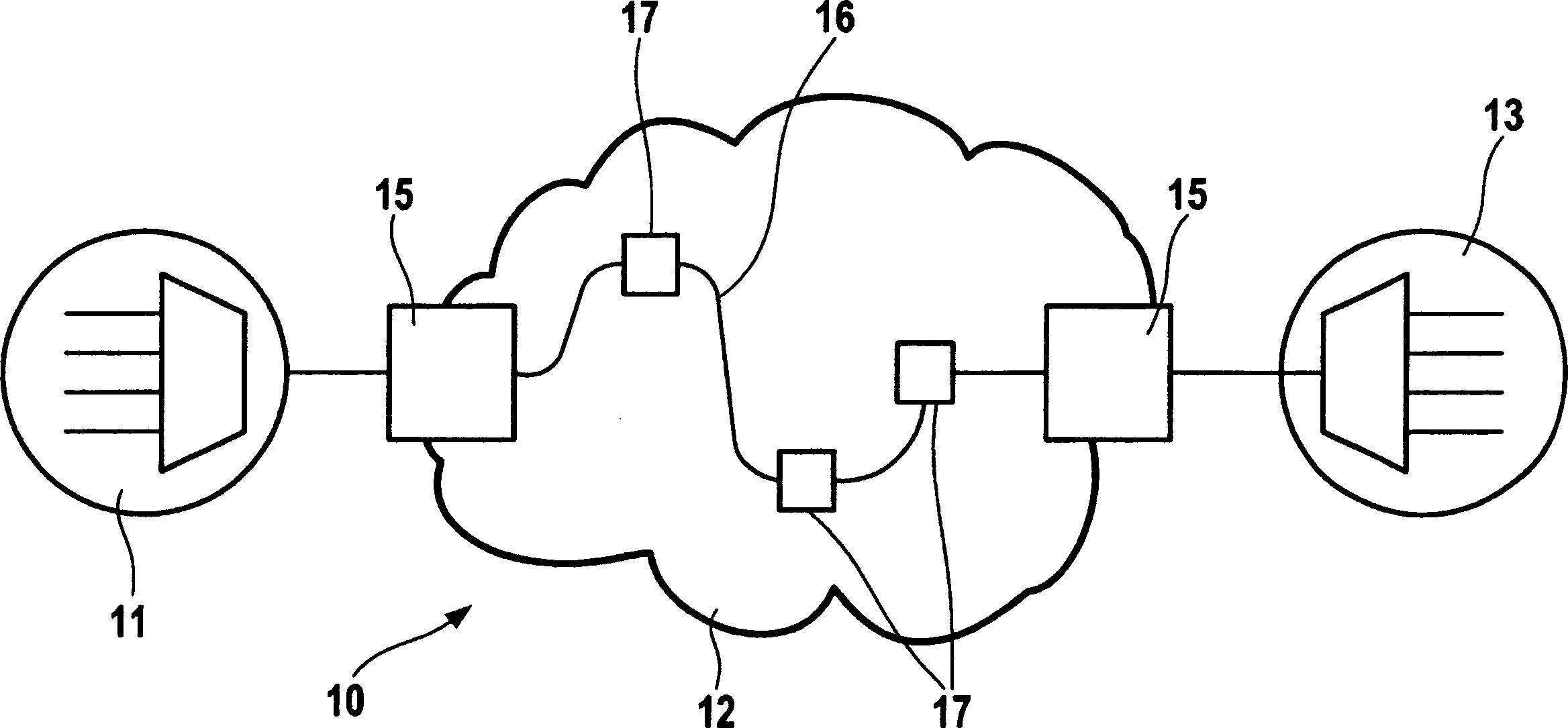
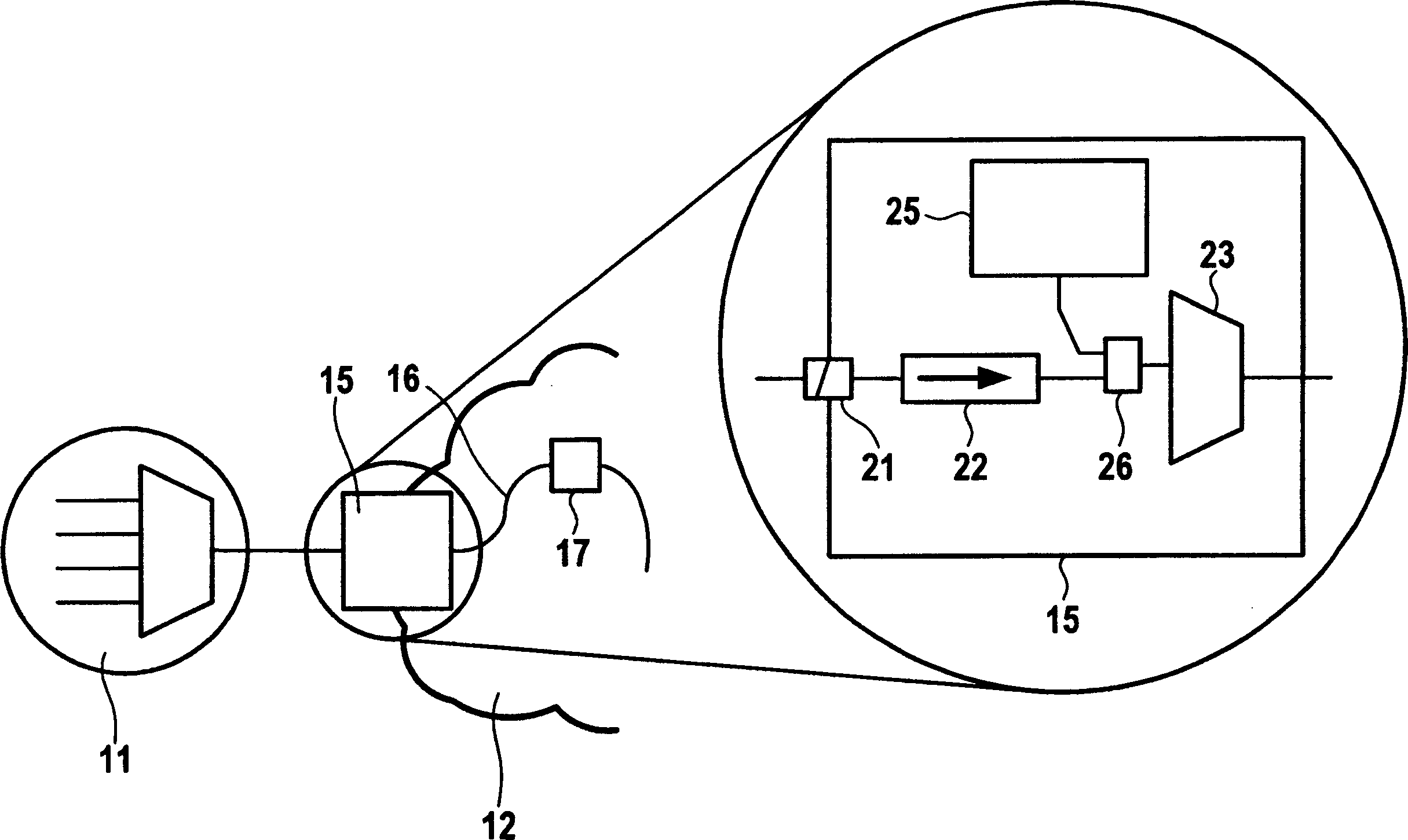
[0018] exist figure 1 In the illustrated communication network 10 comprises a first network configuration 11 , an optical network configuration 12 and a second network configuration 13 . An optical network configuration 12 is connected to each of the first and second network configurations 11 , 13 . Alternatively, only a single network configuration connected to the optical network configuration 12 may be given.
[0019] The first and second network configurations 11, 13 may be implemented as active and / or multiplexed and / or any other type of communication infrastructure. Optical network configurations are built from passive fiber optic infrastructure12. The optical network infrastructure 12 comprises two entry points 15, which establish connections between the optical network configuration 12 and the first and second network configurations 11, 13, respectively. Furthermore, the optical network arrangement 12 comprises an optical path 16 interconnecting the two entry points...
PUM
 Abstract
Description
Claims
Application Information