Transmitting channel correcting method in multiple input multiple output system

A transmission channel, multi-output technology, applied in multi-frequency code system, diversity/multi-antenna system, space transmission diversity and other directions, can solve the problems of communication network increase, increase communication network interference, interference and other problems

Active Publication Date: 2006-11-08
XFUSION DIGITAL TECH CO LTD
View PDF0 Cites 32 Cited by
  • Summary
  • Abstract
  • Description
  • Claims
  • Application Information

AI Technical Summary

Problems solved by technology

[0007] As mentioned above, the transmission correction signal required in the transmission channel calibration process of the prior art MIMO system is time-division injected into the transmission channel, and the method of time-division injecting the transmission correction signal has the following problems: the system needs to provide free time for injecting the transmission correction signal Therefore, it is limited by the application of the transmission channel correction method; since the transmission correction signal and the service signal are time-division multiplexed, and the transmission correction signal may also need to share bandwidth with other control information, therefore, it is necessary to design complex correction timing and Correction algorithm; after the transmission correction signal that is not a business signal is sent to the antenna port through the coupler, the antenna sends the transmission correction signal to the wireless space, which increases unnecessary interference in the communication network
[0008] In summary, since the method of time-division injection of transmission correction signals causes a series of negative effects, the method of using time-division injection of transmission correction signals for MIMO system transmission channel correction is limited by application and requires the design of complex correction algorithms. And add unnecessary interference to the communication network

Method used


Image

  • Transmitting channel correcting method in multiple input multiple output system
  • Transmitting channel correcting method in multiple input multiple output system
  • Transmitting channel correcting method in multiple input multiple output system

Examples


Embodiment Construction

[0037] In order to make the object, technical solution and advantages of the present invention clearer, specific examples are given below to further describe the present invention in detail.

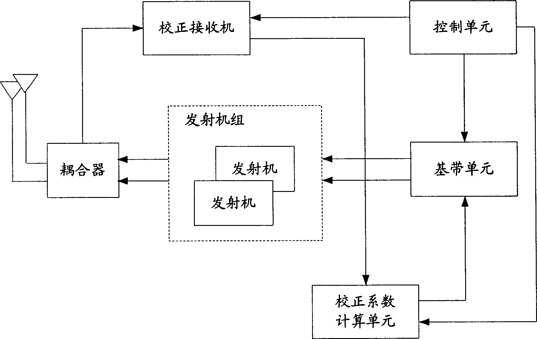
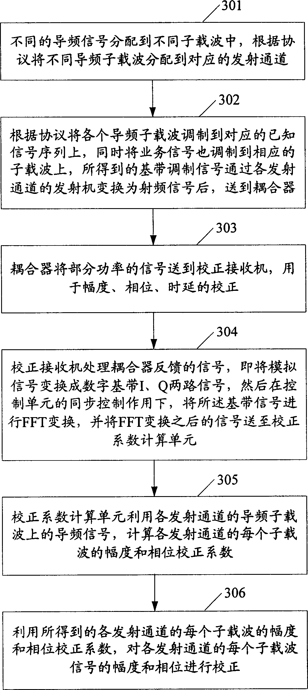
[0038] In a wireless communication system, a transmitting end usually inserts a known pilot signal into a service signal for channel estimation at a receiving end. The present invention uses the pilot signal as the transmission correction signal to correct the transmission channel. The main idea is: after the baseband modulation of the pilot signal and the service signal, it is converted into a radio frequency signal through each transmission channel and sent to the antenna port; Obtain the pilot signal of each transmission channel from the radio frequency signal at the location, and use the obtained pilot signal to obtain the correction coefficient of each transmission channel; use the obtained correction coefficient of each transmission channel to correct the signal of each transmission...


PUM


Abstract

This invention discloses a correction method for emission channels in a MIMO system including: a, carrying out baseband modulation to pilot signals and service signals to get baseband modulation signals to be converted to RF signals by the emission channels to be sent to the antenna interface, b, getting the pilot signals of the emission channels from the signals at the antenna interface to get the correction coefficient of the emission channels, c, utilizing the correction coefficients to correct the channels, which takes the pilot signals as the emission correction signals and the pilot signals are inserted for the channel estimation so it will not influence the network.

Description

technical field [0001] The invention relates to the key technology of multiple-input multiple-output (MIMO), in particular to a transmission channel correction method in the MIMO system. Background technique [0002] Wireless communication systems can receive and transmit signals using MIMO technology. The MIMO technology comprehensively utilizes the information of the wireless channel, and can improve the performance of the wireless communication system in terms of coverage, spectrum utilization and channel capacity. MIMO technology can be used in both base stations (BS) and subscriber stations (SS). For an Orthogonal Frequency Division Multiplexing (OFDM) system or an Orthogonal Frequency Division Multiple Access (OFDMA) system, if MIMO technology is used, system performance can be greatly improved. [0003] At the transmitting end in an actual MIMO system, the amplitude, phase and time delay of each transmitting channel from the baseband to the antenna port are inconsis...

Claims


Application Information

Patent Timeline
Patent Type & Authority Applications(China)
IPC IPC(8): H04B7/06H04L1/06H04L27/26
Inventor 曹爱军杨芳梁叶四清
Owner XFUSION DIGITAL TECH CO LTD
Why Eureka
Try Eureka