
Projection apparatus and distance measuring method for projection apparatus

A projection device and technology for projecting light, applied in the direction of using projection device image reproducer, projection device, color TV parts, etc., can solve problems such as errors

Inactive Publication Date: 2006-11-15
KK TOSHIBA
View PDF2 Cites 9 Cited by
  • Summary
  • Abstract
  • Description
  • Claims
  • Application Information

AI Technical Summary

Problems solved by technology

[0005] However, in the first reference document and the second reference document mentioned above, in the case where the screen to be range-measured or an object serving as a substitute for the screen has a high reflectivity, the reflected light is so strong that it may Error due to the influence of reflected light

Method used


Image

  • Projection apparatus and distance measuring method for projection apparatus
  • Projection apparatus and distance measuring method for projection apparatus
  • Projection apparatus and distance measuring method for projection apparatus

Examples


Embodiment Construction

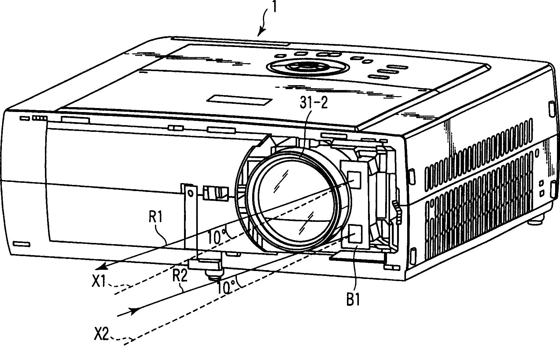
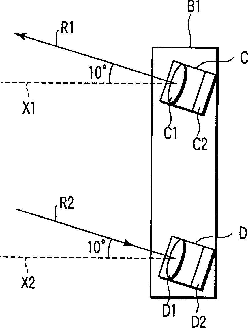
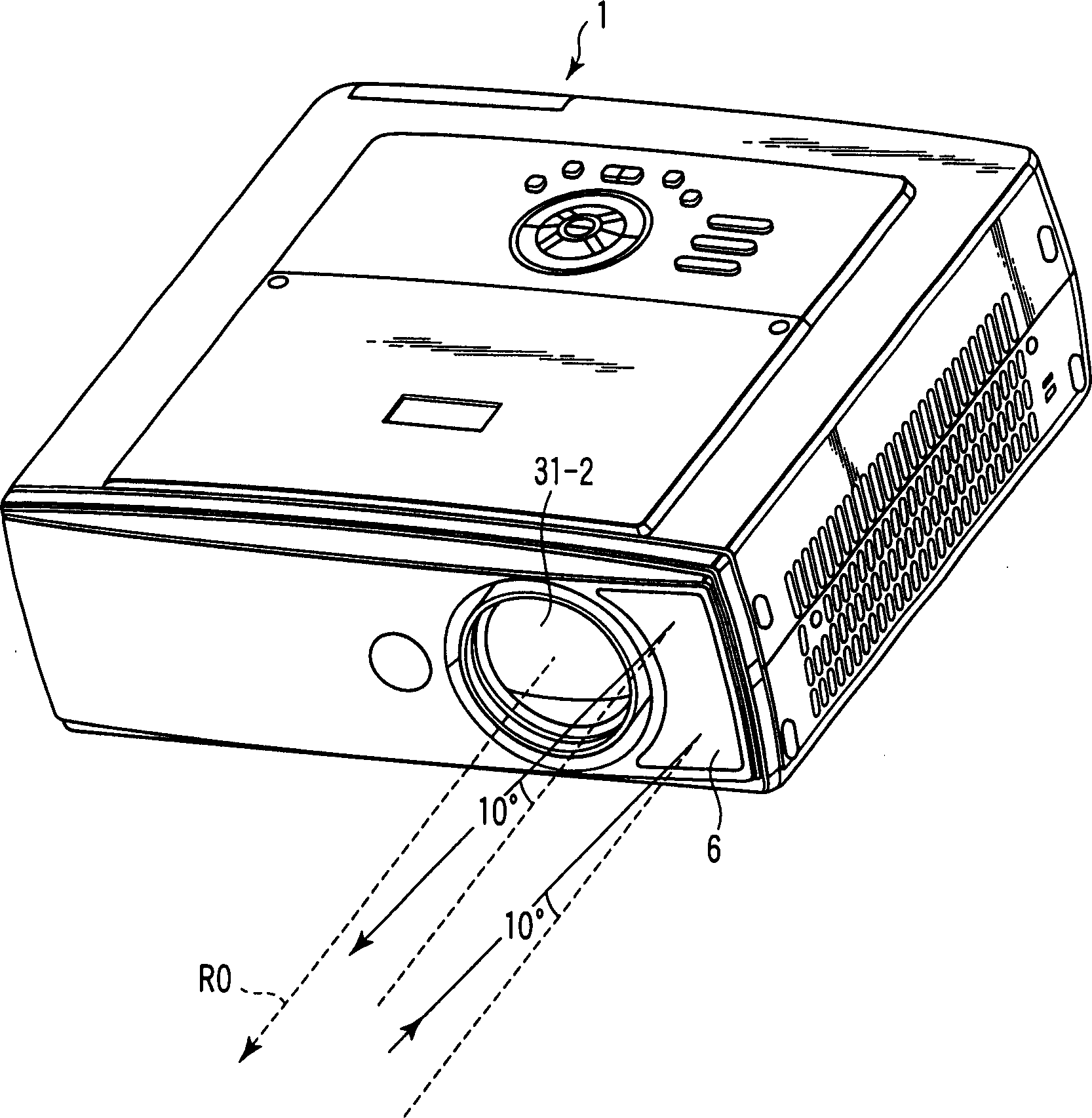
[0023] Various embodiments according to the present invention will be described below with reference to the accompanying drawings. Generally, according to an embodiment of the present invention, the projection device includes: a projection unit, configured to emit projection light onto an object along a first direction; a light emitting unit, configured to irradiate the object along a second direction with rays, wherein the second The direction differs from the first direction by about four (4) degrees to thirty (30) degrees; the light receiving unit is used to receive light in a third direction that differs from the first direction by about four (4) degrees to thirty (30) degrees light reflected from the object to be irradiated; and a control unit for adjusting projection light to be emitted by the projection unit based on the reflected light received by the light receiving unit.

[0024] figure 1 A typical projection device 1 equipped with a distance measuring sensor unit a...


PUM


Abstract

According to one embodiment, a projection apparatus comprises a projection unit (31) to emit projection light on an object in a first direction, a light emitting unit (C) to irradiate the object with a ray in a second direction which is different from the first direction by approximately four (4) degrees to thirty (30) degrees, a light receiving unit (D) to receive reflected light from the object from the ray irradiated by the light emitting unit in a third direction which is different from the first direction by approximately four (4) degrees to thirty (30) degrees, and a control unit (2, 27, 39) to adjust the projection light to be emitted by the projection unit in accordance with the reflected light received by the light receiving unit.

Description

technical field [0001] One embodiment of the invention relates to devices such as liquid crystal projectors or DLP TM A projection device of a projector, and a distance measuring method of the projection device for measuring the distance between the projection device and a screen onto which projection light is emitted. Background technique [0002] In recent years, a large number of digital video image devices have been put on the market, and, for example, there is a projection device using a light source lamp, such as a liquid crystal projector or a DLP TM projector. A projection device such as a liquid crystal projector measures a distance from the projection device to a screen or an object, and performs focus adjustment based on the measured distance. Similarly, in order to measure the distance from the projection device to the screen, infrared rays are used in the projection device. [0003] Japanese Patent Application Laid-Open Publication No. 11-264963 (hereinafter ...

Claims


Application Information

Patent Timeline
Patent Type & Authority Applications(China)
IPC IPC(8): H04N5/74H04N9/31
CPCG03B21/53H04N9/317G03B21/142
Inventor 齐藤公昭
Owner KK TOSHIBA
Learn More