Line single-phase earth fault positioning method based on before-and-after fault voltage phase characteristic

A single-phase-to-ground fault, voltage-phase technology, applied in fault location, information technology support system, etc., can solve the problems of high application cost, high sampling rate requirements, fault location results exceeding the full length of the line, etc., to simplify the design The effect of manufacturing, high ranging accuracy

Active Publication Date: 2014-04-30
STATE GRID PUTIAN ELECTRIC POWER SUPPLY +2
View PDF6 Cites 8 Cited by
  • Summary
  • Abstract
  • Description
  • Claims
  • Application Information

AI Technical Summary

Problems solved by technology

The traveling wave method utilizes the transmission properties of fault transient traveling waves to perform single-ended fault location. It has high precision and is not affected by the operation mode and excessive resistance. However, it requires a high sampling rate, requires a special wave recording device, and has high application costs.
The impedance method uses the voltage and current after the fault to calculate the fault loop impedance, and performs single-ended fault location according to the characteristic that the line length is proportional to the impedance. It is simple and reliable, but the fault location accuracy is seriously affected by factors such as transition resistance and load current. Especially when the transition resistance is large, the result of impedance method distance measurement will seriously deviate from the real fault distance, and even the fault distance measurement fails or the fault distance measurement result exceeds the entire length of the line, which cannot provide accurate fault location information, making fault line inspection difficult. It is conducive to the rapid elimination of transmission line faults and the rapid restoration of line power supply

Method used


Image

  • Line single-phase earth fault positioning method based on before-and-after fault voltage phase characteristic
  • Line single-phase earth fault positioning method based on before-and-after fault voltage phase characteristic
  • Line single-phase earth fault positioning method based on before-and-after fault voltage phase characteristic

Examples


Embodiment Construction

[0012] The technical solution of the present invention will be further described in detail according to the accompanying drawings.

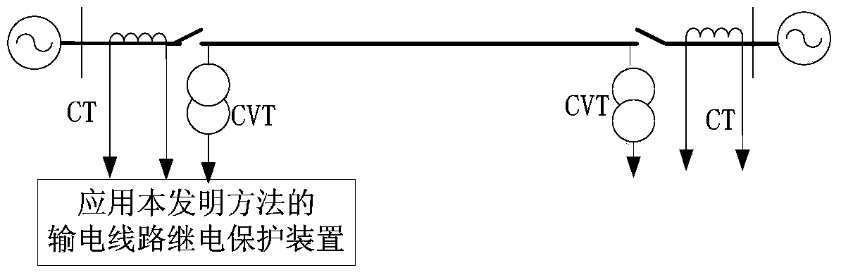
[0013] figure 1 It is a schematic diagram of the line transmission system applying the present invention. figure 1 The CVT is a voltage transformer, and the CT is a current transformer. After the AC analog output from the voltage transformer and the current transformer is converted into a sampling digital signal, it is transmitted to the transmission line protection device applying the method of the present invention.

[0014] The transmission line relay protection device measures the fault phase voltage at the transmission line protection installation fault phase current and zero sequence current Measure the other two normal phase voltages Among them, φαβ=ACB, BAC, CBA phase, that is, when φ=A phase, α=C phase, β=B phase; when φ=B phase, α=A phase, β=C phase; when φ= In C phase, α=B phase, β=A phase.

[0015] The transmission line rela...


PUM


Abstract

The invention discloses a line single-phase earth fault positioning method based on the before-and-after fault voltage phase characteristic. The line single-phase earth fault positioning method includes the steps of firstly, measuring a fault-phase voltage, a fault-phase current and a zero sequence current at the protection installation position of an electric transmission line, measuring voltages of the other two normal phases, calculating a fault-phase voltage when the electric transmission line normally operates in real time through the voltages of the two normal phases after line single-phase earth faults, sequentially calculating a phase angle of the fault-phase voltage of each point on the electric transmission line and the fault-phase voltage, when the electric transmission line normally operates, of the point of the electric transmission line in the mode of beginning with the protection installation position of the power transmission line and gradually increasing with a fixed step length, and achieving accurate ranging of the electric transmission line single-phase earth faults through the characteristic that the angles of the fault-phase voltages in front of and behind a fault point and the fault-phase voltage when the electric transmission line normally operates can generate phase step changes. According to the line single-phase earth fault positioning method, the fault-phase voltage before the line single-phase earth faults is not required to be memorized, a loop for keeping the voltage before the line faults is not required to be set, influences of transition resistance and a load current are eliminated, and the ranging accuracy is high.

Description

technical field [0001] The invention relates to the technical field of electric power system relay protection, in particular to a method for locating single-phase grounding faults of lines based on voltage phase characteristics before and after faults. Background technique [0002] The single-ended fault location method only uses the electrical quantity at one end of the transmission line for fault location, does not require communication and data synchronization equipment, has low operating costs and stable algorithms, and has been widely used in transmission lines. Single-ended fault location methods are mainly divided into traveling wave method and impedance method. The traveling wave method utilizes the transmission properties of fault transient traveling waves to perform single-ended fault location. It has high precision and is not affected by the operation mode and excessive resistance. However, it requires a high sampling rate, requires a special wave recording device...

Claims


Application Information

Patent Timeline
Patent Type & Authority Applications(China)
IPC IPC(8): G01R31/08
CPCY04S10/52
Inventor 林富洪
Owner STATE GRID PUTIAN ELECTRIC POWER SUPPLY
Why Eureka
Try Eureka