Electromagnetic distance measurement method and system, signal receiving terminal and signal transmitting terminal

A technology of receiving terminal and electromagnetic signal, applied in the field of radio frequency, can solve the problems such as the inability to eliminate the interference channel and the inaccurate ranging of the receiving terminal.

Inactive Publication Date: 2015-06-03
NATIONZ TECH INC
View PDF5 Cites 9 Cited by
  • Summary
  • Abstract
  • Description
  • Claims
  • Application Information

AI Technical Summary

Problems solved by technology

[0003] The present invention provides an electromagnetic ranging method, system, receiving terminal, and sending terminal, which solves the problem that the interference channel cannot be eliminated in the prior art, so that the sending terminal uses the interference channel to transmit electromagnetic signals, thereby enabling the receiving terminal to measure distance inaccurate question

Method used


Image

  • Electromagnetic distance measurement method and system, signal receiving terminal and signal transmitting terminal
  • Electromagnetic distance measurement method and system, signal receiving terminal and signal transmitting terminal
  • Electromagnetic distance measurement method and system, signal receiving terminal and signal transmitting terminal

Examples


Embodiment 1

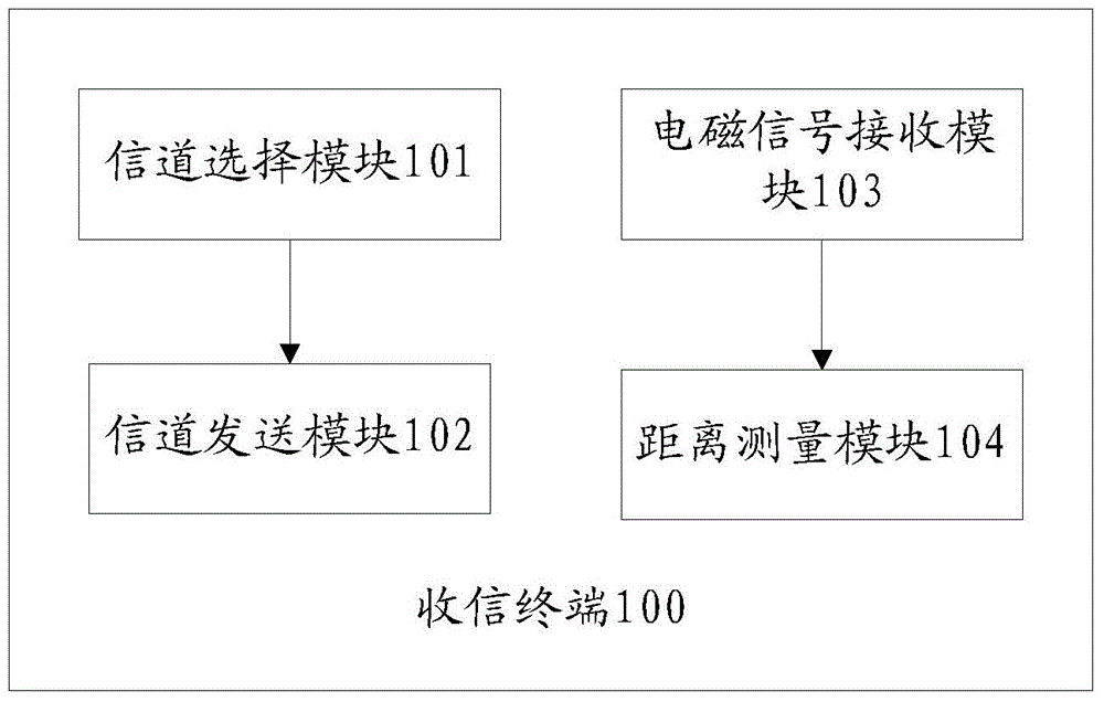
[0046] Such as figure 1 Shown is a structural diagram of a receiving terminal of the present invention, please refer to figure 1 , the receiving terminal 100 includes: a channel selection module 101, a channel transmission module 102, an electromagnetic signal receiving module 103 and a distance determination module 104, and the channel selection module 101 is used to select a better channel from a plurality of available working channels according to preset rules Working channel; channel sending module 102, used to send the identification information of the better working channel selected by the channel selection module to the peer device; electromagnetic signal receiving module 103, used to receive the peer device using the better The electromagnetic signal sent by the optimal working channel; the distance determination module 104, configured to determine the distance between the receiving terminal and the peer device according to the electromagnetic signal sent by the peer d...

Embodiment 2

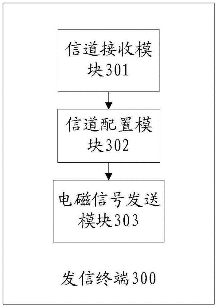
[0057] Such as image 3 It is a structural diagram of a sending terminal in the present invention. See image 3 , the sending terminal 300 mainly includes a channel receiving module 301, a channel configuration module 302 and an electromagnetic signal sending module 303, the channel receiving module 301 is used to receive the identification information of the optimal working channel sent by the peer device; the channel configuration module 302, It is used to configure the working channel of the sending terminal according to the optimal working channel received by the channel receiving module; the electromagnetic signal sending module 303 is used to send an electromagnetic signal to the peer device by using the working channel configured by the channel configuration module, The electromagnetic signal is used by the peer device to determine the distance between them.

[0058] In one embodiment, the channel receiving module 301 can be a receiving terminal in existing communicat...

Embodiment 3

[0061] Such as Figure 4 Shown is a flowchart of an electromagnetic ranging method, please participate Figure 4 , after ranging starts:

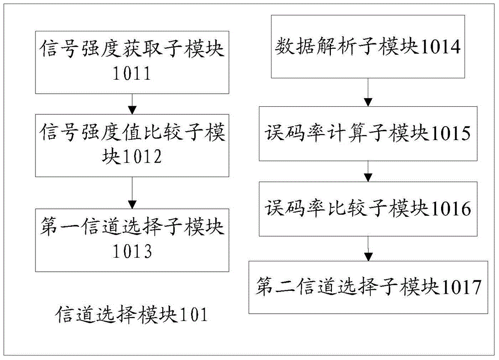
[0062] S401: Select a better working channel from multiple available working channels according to preset rules. Specifically, receiving electromagnetic signals on multiple available working channels is to scan all working channels for ranging Environmental noise scanning; obtain the environmental signal strength value on a plurality of available working channels; compare the environmental signal strength value with a first preset value, the first preset value represents the environmental signal-to-noise ratio of the environmental signal strength Standard value, if the environmental signal strength value is greater than the first preset value, the channel interference corresponding to the environmental signal strength value is relatively large, which is not suitable for accurate ranging; select an environmental signal that is less than or ...


PUM


Abstract

The invention provides an electromagnetic distance measurement method and system, a signal receiving terminal and a signal transmitting terminal. The signal receiving terminal comprises a channel selection module, a channel transmitting module, an electromagnetic signal receiving module and a distance determination module, wherein the channel selection module is selecting a preferred working channel from a plurality of available working channels according to preset rules; the channel transmitting module is used for transmitting identification information of the preferred working channel to opposite equipment; the electromagnetic receiving module is used for receiving electromagnetic signals transmitted by the opposite equipment by using the preferred working channel; the distance determination module is used for determining a distance between the signal receiving terminal and the opposite equipment according to the electromagnetic signals. The signal transmitting terminal comprises a channel receiving module, a channel configuration module and an electromagnetic signal transmitting module, wherein the channel receiving module is used for receiving identification information of the preferred working channel transmitted by opposite equipment; the channel configuration module is used for configuring the working channel of the signal transmitting terminal according to the preferred working channel; the electromagnetic signal transmitting module is used for transmitting the electromagnetic signals to the opposite equipment by using the configured working channel, and the electromagnetic signals are used for determining the distance between the signal transmitting terminal and the opposite equipment The scheme has the advantages that the interference channel is removed, the preferred working channel is used and the distance measurement is enabled to be more accurate.

Description

technical field [0001] The present invention relates to the field of radio frequency technology, in particular to an electromagnetic ranging method, system, receiving terminal and sending terminal. Background technique [0002] With the increasing demand for positioning using radio frequency technology, electromagnetic ranging technology has developed rapidly. One of the ranging technologies is: NFER (Near-Field Electromagnetic Ranging), which stands for near-field electromagnetic ranging. Compared with traditional radio frequency ranging technology, the biggest advantage of this technology is that it can penetrate obstacles for distance measurement under non-line of sight (Non-Line of Sight) conditions. The basic principle is that within the distance between the sending terminal and the receiving terminal in the near field, the phase difference between the transmitted electrical (E-field) signal and magnetic (H-field) signal changes with the increase of the distance, so th...

Claims


Application Information

Patent Timeline
Patent Type & Authority Applications(China)
IPC IPC(8): G01S11/02
CPCG01S11/02
Inventor 廖伟军
Owner NATIONZ TECH INC
Why Eureka
Try Eureka