Virtual wall system of self-walking apparatus

A virtual wall and self-propelled technology, applied in the field of virtual wall system, can solve problems such as forgetting to unplug the plug and obstacles

Inactive Publication Date: 2006-11-22
中弘智能高科技(深圳)有限公司
View PDF1 Cites 17 Cited by
  • Summary
  • Abstract
  • Description
  • Claims
  • Application Information

AI Technical Summary

Problems solved by technology

[0003] However, in the aforementioned prior art, during operation, the light source transmitter must continuously emit light to ensure that the light source receiver on the self-propelled vacuum cleaner will continue to use power when the self-propelled vacuum cleane...

Method used


Image

  • Virtual wall system of self-walking apparatus
  • Virtual wall system of self-walking apparatus
  • Virtual wall system of self-walking apparatus

Examples


Embodiment Construction

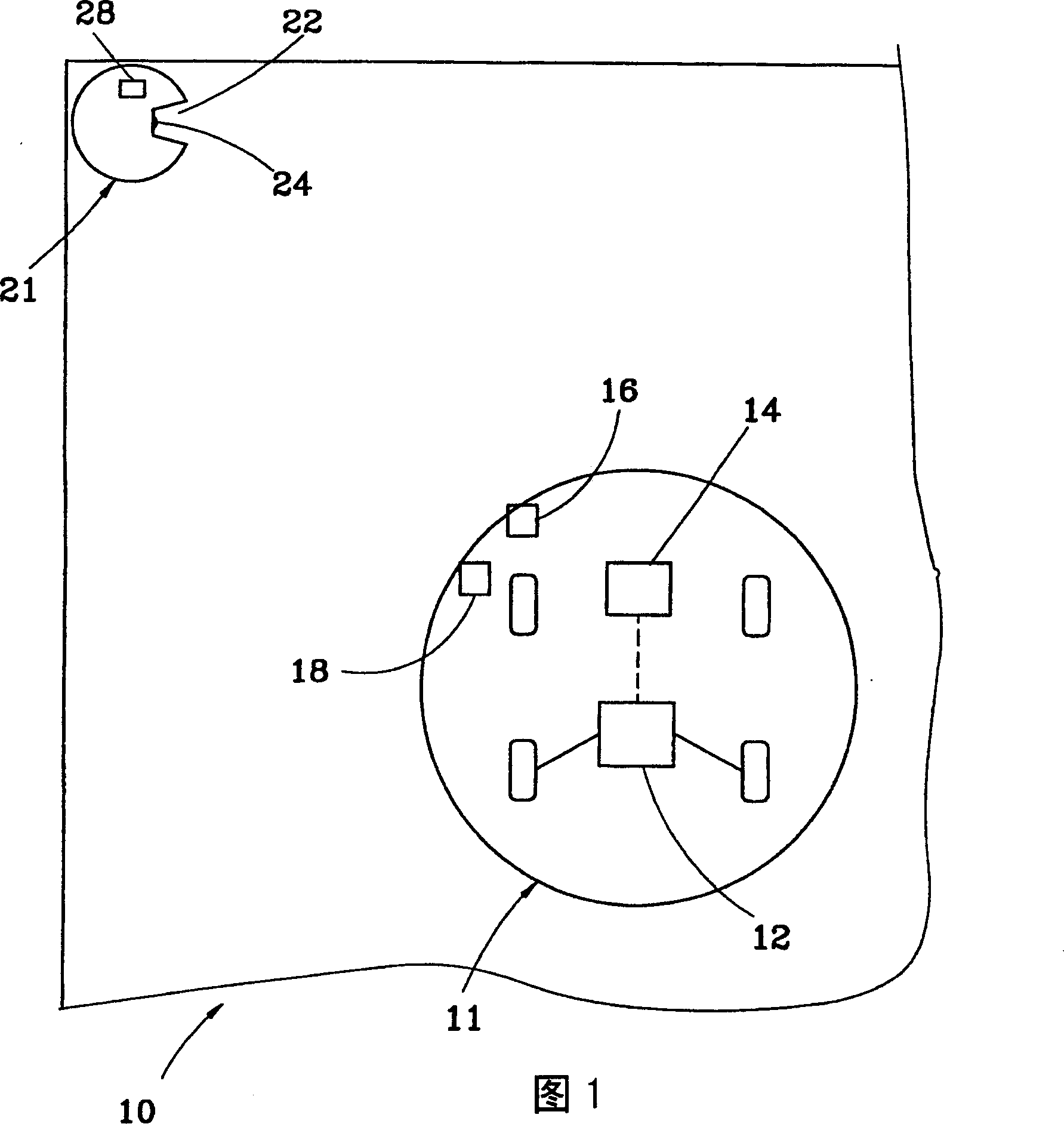
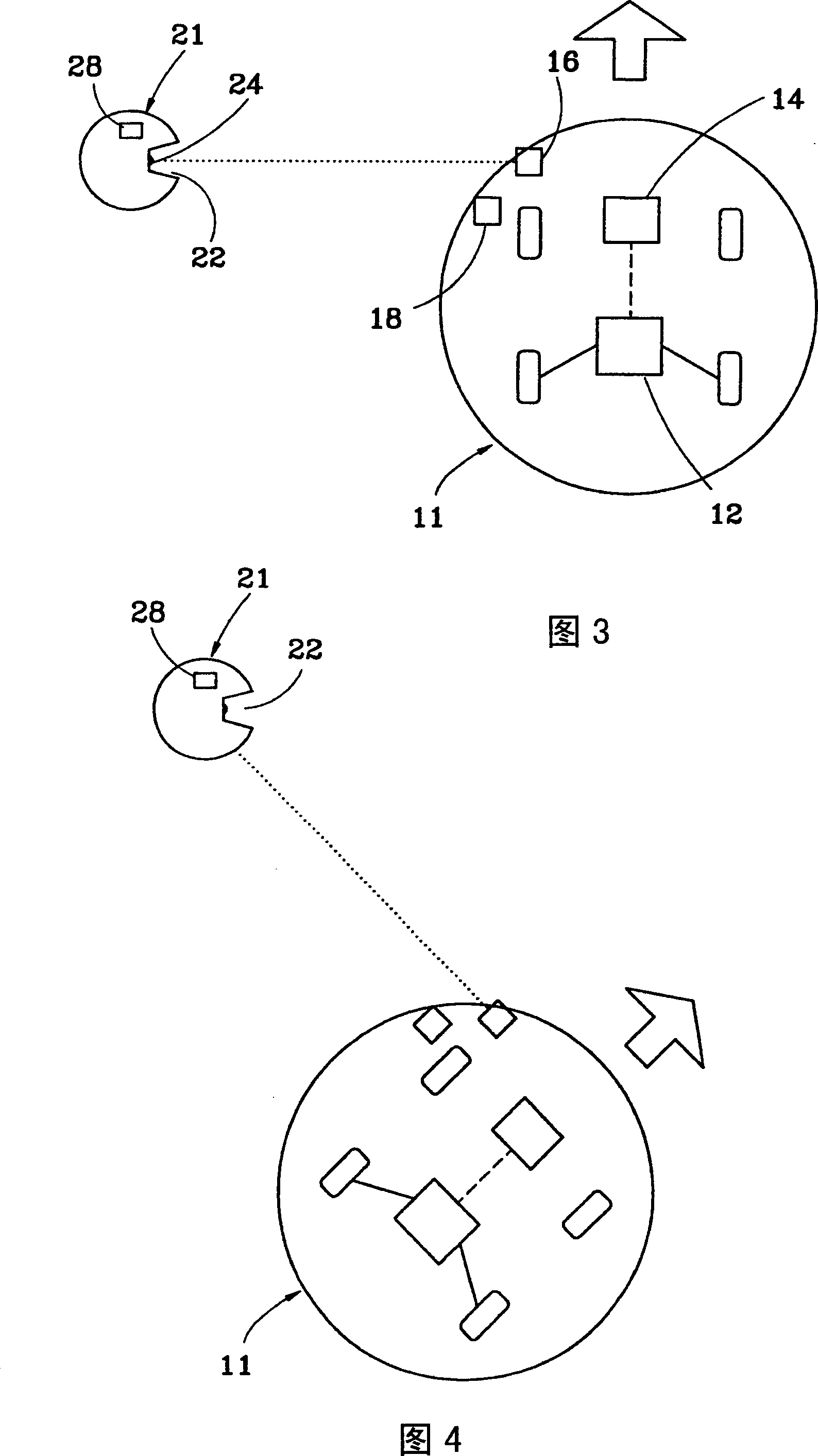
[0023] Figure 1 to figure 2 As shown, the virtual wall system 10 of a self-propelled device provided by the first preferred embodiment of the present invention is mainly composed of a self-propelled device 11 and a virtual wall generating device 21, wherein:

[0024] The self-propelled device 11 has a steering device 12 that can turn towards at least one direction, and has a control device 14 connected to the steering device 12 for controlling the steering of the steering device 12, and has at least one signal transmitter 16, It is installed on one side of the self-propelled device 11 and transmits a signal to one side of the self-propelled device 11. In this embodiment, an optical signal is used as an example, and an acoustic wave receiver 18 is provided for receiving the acoustic wave signal.

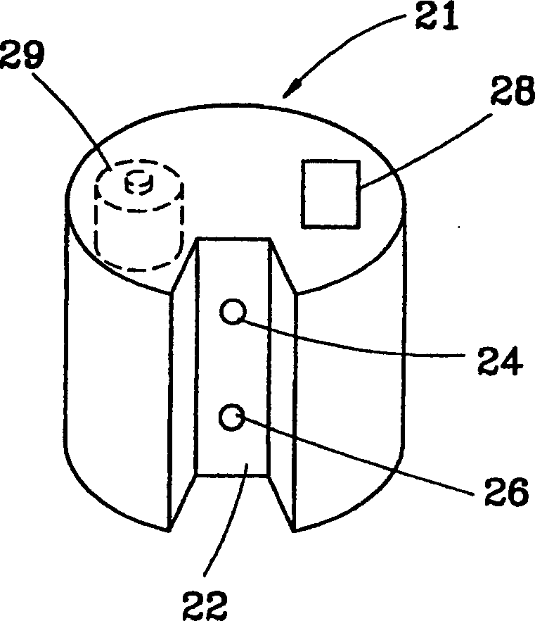
[0025] The virtual wall generating device 21 is placed on the plane on which the self-propelled device 11 travels, such as the ground. The virtual wall generating device 21 has at lea...


PUM


Abstract

The disclosed virtual wall system for a self-walk device comprises: a self-walk device with a steering device, a connected controller, at least a signal emitter, and a receiver; at least a virtual wall generator with a signal receiver, an audio emitter, a signal controller. Wherein, then walking, the signal receiver receives signal, the controller controls the audio generator to produce audio, the audio receiver receives the signal, and the controller forces the device steering.

Description

technical field [0001] The present invention is related to the control of the self-propelled device, in particular to a virtual wall system of the self-propelled device. Background technique [0002] Existing self-propelled devices, such as self-propelled robots, or self-propelled vehicles, or self-propelled vacuum cleaners, etc., all determine the direction, speed and distance of the advance according to the pre-input route, or by means of image recognition, and , such as the technology disclosed in US Patent Early Publication No. US 2004 / 0,111,184, which mainly discloses a technology in which a self-propelled vacuum cleaner uses light beams as a virtual wall. The self-propelled vacuum cleaner has a light source receiver to receive the light beam. When the self-propelled vacuum cleaner travels to receive the light beam, it sends a turning signal to reach the limit of the light beam that does not exceed the light source transmitter. position, which in turn has the effect of...

Claims


Application Information

Patent Timeline
IPC IPC(8): G01S3/80
Inventor 邱顶殷
Owner 中弘智能高科技(深圳)有限公司
Why Eureka
Try Eureka