Method for determining location on display surface and interactive display system

一种显示面、任意位置的技术,应用在字符和模式识别、静态指示器、阴极射线管指示器等方向,能够解决不适用显示模态等问题

Inactive Publication Date: 2006-12-06
MITSUBISHI ELECTRIC CORP
View PDF2 Cites 19 Cited by
  • Summary
  • Abstract
  • Description
  • Claims
  • Application Information

AI Technical Summary

Problems solved by technology

These pixel-based displays are not scanned, so traditional light pen technology of raster-scan based timing is not suitable for these newer display modalities

Method used


Image

  • Method for determining location on display surface and interactive display system
  • Method for determining location on display surface and interactive display system
  • Method for determining location on display surface and interactive display system

Examples


Embodiment Construction

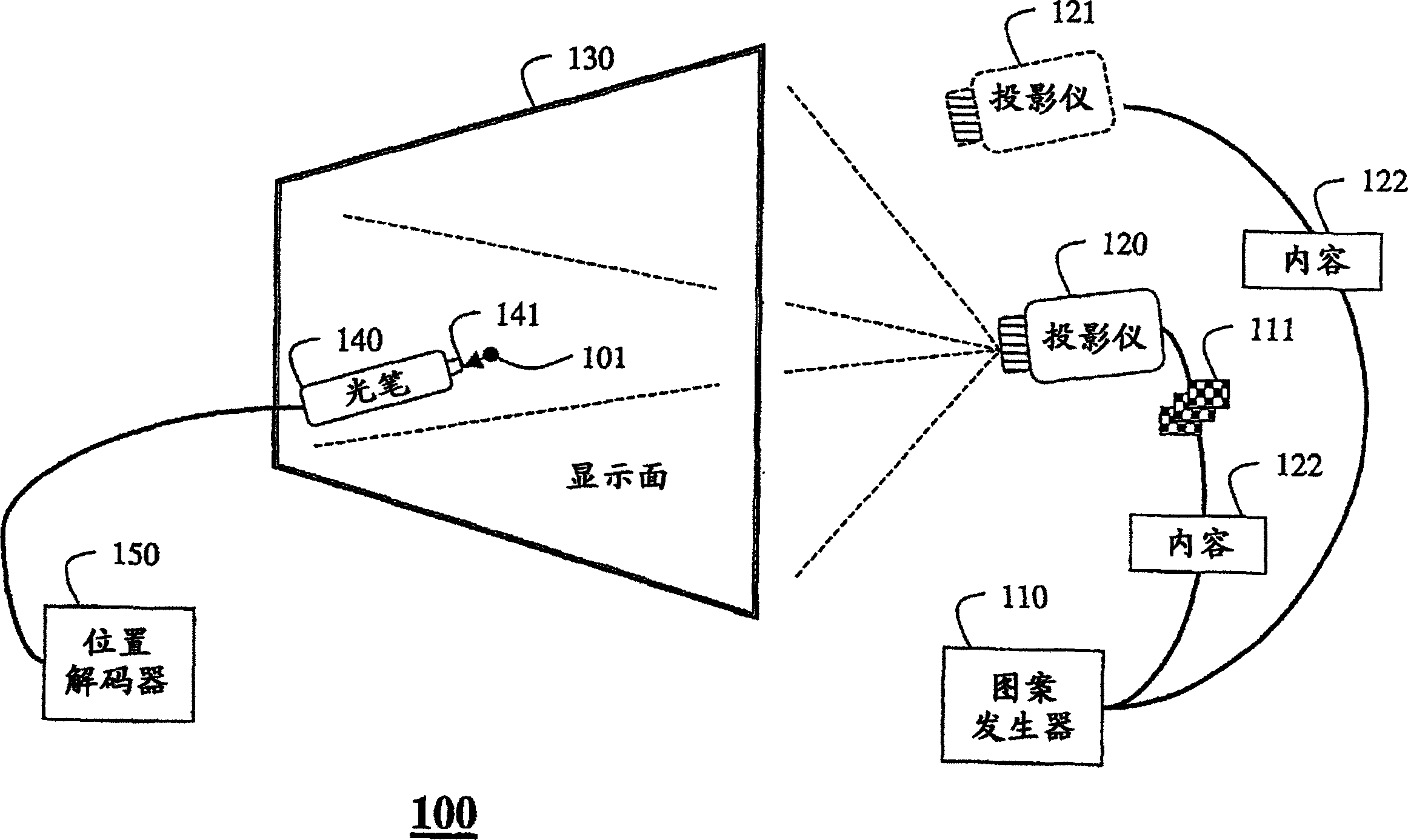
[0022] figure 1 A light pen system 100 for a pixel based display is shown. The system includes a pattern and content generator 110 coupled to an image generator 120, such as a projector. The image generator presents a series of patterns 111 on the display surface 130 . In the preferred embodiment, the display surface is a pixel based display surface rather than a raster scan display surface, although the system could also work with raster scan displays. The system also includes a light pen 140 coupled to a position decoder 150 . Its task is to determine the 2D coordinates of any position 101 on the display surface 130 .

[0023] The image generator 120 can use LCD screens in front or rear projection mode, digital mirror arrays, liquid crystal on silicon (LCOS) and organic LED technologies. It should be noted that the present invention can also be used with conventional CRT displays. The light pen may use a single light sensor 141 or an array of sensors like in a camera, s...


PUM


Abstract

An interactive display system includes a pixel-based display surface and a light pen. A sequence of patterns is projected onto the display surface. The sequence of patterns has a unique sequence of light intensities for each location of the display surface. Intensities of light at an arbitrary location are sensed by the light pen while projecting the sequence of patterns. The intensities of light are decoded to determine coordinates of the arbitrary location.

Description

technical field [0001] This invention relates to input devices for interacting with display systems, and more particularly to light pens for use with such display systems. Background technique [0002] Light pens are commonly used as input devices with graphical user interfaces, for a brief history see Myers, "A Brief History of Human Computer Interaction Technology", ACM Interactions, Vol.5, no.2, pp.44-54, March 1998. Although light pens have been used since 1954, it was Ivan Sutherland's work at Lincoln Laboratories that popularized the use of light pens with computers, Sutherland, "Sketchpad: The First Interactive Computer Graphics", Ph.D. Thesis, MIT, 1963. [0003] As an input device, a light pen has several advantages over a mouse. The mouse is an indirect input device. Movement of the mouse on the horizontal plane results in movement of the cursor on the vertical display. The amount of mouse and cursor movement, as well as the speed of movement, may vary. On the ...

Claims


Application Information

Patent Timeline
Patent Type & Authority Applications(China)
IPC IPC(8): G06F3/033G06F3/00G06F3/042G06K9/00G09G5/00
CPCG06F3/03542G06F3/0321
Inventor 保罗·H.·戴尔兹达林·L.·利莱弥施·拉斯卡约翰尼·C.·李
Owner MITSUBISHI ELECTRIC CORP
Why Eureka
Try Eureka