Identification of object on interactive display surface by identifying coded pattern

a technology of object identification and coded pattern, applied in the field of encoded patterns, can solve the problems of not being able to address many of the problems of prior art visual codes designed to work with high-resolution scanners, and it is much more difficult to decode visual codes on objects within images, so as to achieve the effect of reducing nois

Inactive Publication Date: 2007-04-17
MICROSOFT TECH LICENSING LLC
View PDF3 Cites 139 Cited by
  • Summary
  • Abstract
  • Description
  • Claims
  • Application Information

AI Technical Summary

Benefits of technology

[0008]One of the advantages of the present invention is that it enables an appropriate identifier to be employed for an object that is used with an interactive display table, based upon the shape and size of the object, the limitations imposed by the resolution of the vision sensing system used to image the identifier and the requirements of the software application with which the object is used. One aspect of the invention is thus directed to a two-dimensional identifier that is applied to an object for encoding a value so that the value is determinable when the two-dimensional identifier is placed adjacent to the surface sensing system of the interactive table. The two-dimensional identifier includes a cue component having a contiguous area of a detectable material to which the surface sensing system is responsive. The cue component is approximated as an ellipse when detected by the surface sensing system, and the ellipse has axes that indicate an orientation of the two-dimensional identifier relative to a coordinate system of the surface sensing system. A code portion of the identifier is disposed in a predefined location relative to the cue component. The code portion encodes the value with at least one binary element that is detectable by the surface sensing system. Also included is a border region that encompasses the cue component and the code portion. The border region includes a non-detectable material that is not sensed as part of the two-dimensional identifier by the surface sensing system and which functions as an interference mask around the cue component and the code portion, to minimize noise. The detectable material comprises a reflective material that reflects infrared light to which the surface sensing system responds.

Problems solved by technology

In contrast, it is much more difficult to decode a visual code on an object within a image, particularly, when the image is of a relatively large surface, such as the display surface of an interactive display.
However, given the limitations on resolution and other constraints mentioned above, it is likely that many of the prior art visual codes designed to work with high resolution scanners will not be suitable for use with a vision system that must use reflected IR light in an image of an entire display surface to read a visual code applied to a relatively small object in the image.
The prior art does not address many of these problems, which are more specific to a diffusing display surface and vision sensing system, as described above.

Method used


Image

  • Identification of object on interactive display surface by identifying coded pattern
  • Identification of object on interactive display surface by identifying coded pattern
  • Identification of object on interactive display surface by identifying coded pattern

Examples


second embodiment

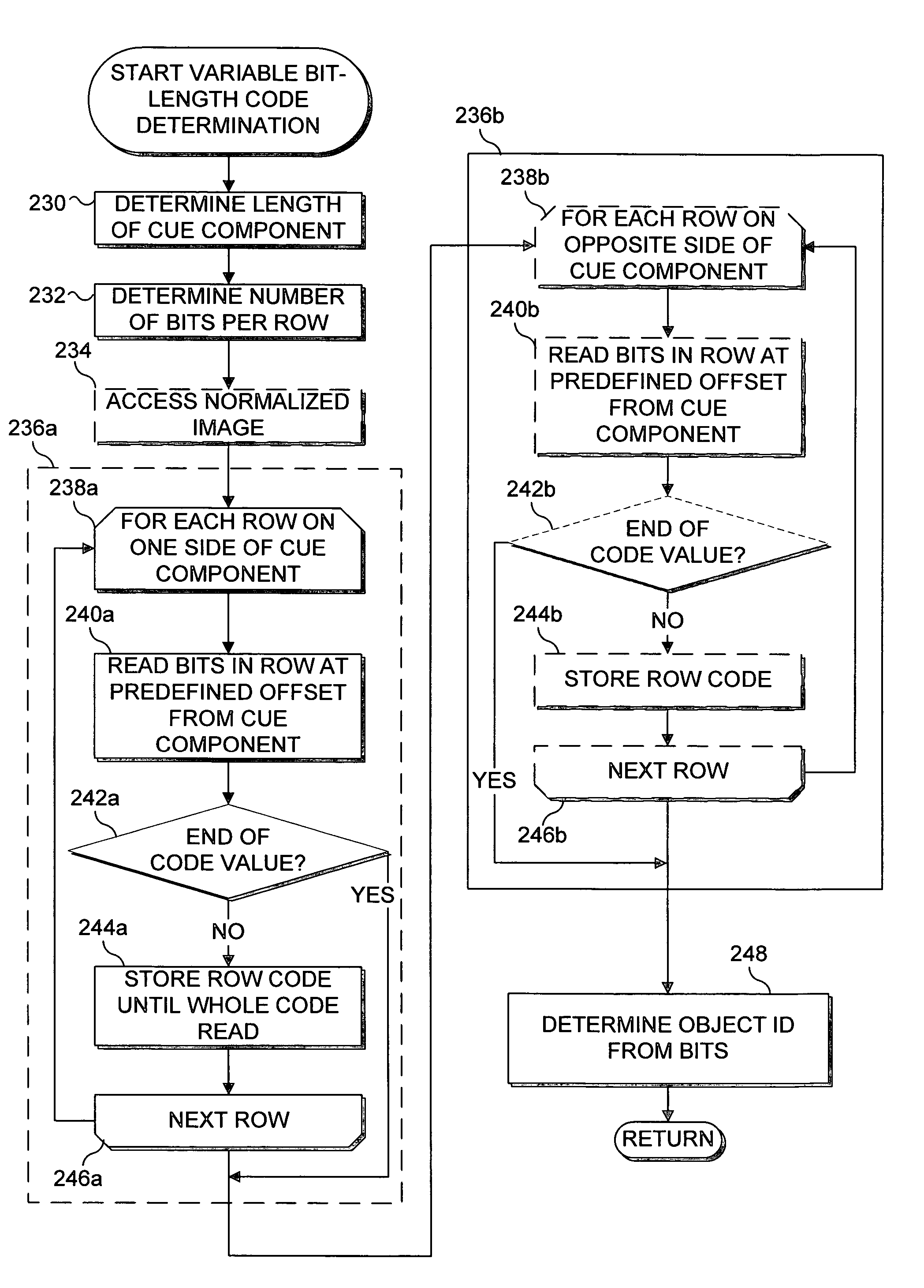
[0056]Having determined the position and orientation of the connected component, the image processing module may perform one or more optional decision steps to facilitate determining the code type and value. In one embodiment, optional decision steps 106, 110, 114, 118, and 120 are not used and the process flows sequentially from step 104 through code determining steps 108, 112, 116, 122, 124, to a step 126 that ranks the results of the code determinations and selects the closest code type based on statistical analysis. In a second embodiment, these optional decision steps are used to select the code determining steps that should be executed. For example, an optional decision step 106 dictates whether a code determining step 108 should be executed. This embodiment thus functions as a filter to reduce the computations required for code detection.

[0057]To ensure a code type is not inadvertently discarded, a combination of the above techniques may be used. The combined technique may em...

first embodiment

[0063]In optional decision step 120, the image processing module tests the connected component for nearby code bits. If the connected component has disconnected bits within a predetermined distance and orientation (i.e., the connected component has nearby code bits), then the image processing module continues at step 122 to determine the matrix code. Details for determining the matrix code are discussed below with regard to FIGS. 11 and 12. After determining the matrix code or if the connected component does not have disconnected bits within a predetermined distance and orientation (i.e., the connected component does not have nearby code bits), then the image processing module continues at step 124 to determine the gray scale code. Details for determining the gray scale code are discussed below with regard to FIGS. 13, 14, and 15. (Note that the logic flow from step 122 to step 124 refers to the sequential logic flow of the )

[0064]In step 126, the image processing module ranks the r...


PUM


Abstract

A coded pattern applied to an object is identified when the object is placed on a display surface of an interactive display. The coded pattern is detected in an image of the display surface produced in response to reflected infrared (IR) light received from the coded pattern by an IR video camera disposed on an opposite side of the display surface from the object. The coded pattern can be either a circular, linear, matrix, variable bit length matrix, multi-level matrix, black / white (binary), or gray scale pattern. The coded pattern serves as an identifier of the object and includes a cue component and a code portion disposed in a predefined location relative to the cue component. A border region encompasses the cue component and the code portion and masks undesired noise that might interfere with decoding the code portion.

Description

FIELD OF THE INVENTION[0001]The present invention generally pertains to the use of encoded patterns to optically identify objects, and more specifically, pertains to various encoded patterns that can be applied to an object to enable the object to be identified based on infrared light reflected from the pattern when the object is placed on or near the surface of an interactive display surface.BACKGROUND OF THE INVENTION[0002]Visual codes such as UPC symbols are commonly used to associate a unique identifier (a number or binary bit code) with a given physical object. This unique identifier is detected by employing image processing techniques that analyze the arrangement of parts of the visual pattern printed on the object. In designing such visual coding schemes, it is important to consider whether the pattern may be easily detected by imaging the object, the ease with which the identifier may be recovered from the pattern once the pattern is located in the image, and various feature...

Claims


Application Information

Patent Timeline
Patent Type & Authority Patents(United States)
IPC IPC(8): G06K19/06G06K7/00
CPCG06K19/06009G06K19/06131G06K9/3216G06K19/06168G06K7/1095G06V10/245
Inventor WILSON, ANDREW D.
Owner MICROSOFT TECH LICENSING LLC
Why Eureka
Try Eureka