Three dimensional interactive display

a three-dimensional interactive display and display technology, applied in the field of data input devices, can solve the problems of not being immediately apparent whether the computer response to the manual input accurately reflects or inaccurately reflects the intended input, and all of the manual input devices are relatively disconnected from the response, so as to improve the coordination of manual input and displayed respons

Inactive Publication Date: 2005-01-25
NASA
View PDF13 Cites 136 Cited by
  • Summary
  • Abstract
  • Description
  • Claims
  • Application Information

AI Technical Summary

Benefits of technology

It is a purpose of the present invention is to improve manual input to displayed response coordination.

Problems solved by technology

However, all of these manual input devices are relatively disconnected from the response to the input that is being displayed by the computer.
Thus, it often may not be immediately apparent whether the computer response to the manual input accurately reflects or inaccurately reflects the intended input.

Method used


Image

  • Three dimensional interactive display
  • Three dimensional interactive display
  • Three dimensional interactive display

Examples


Embodiment Construction

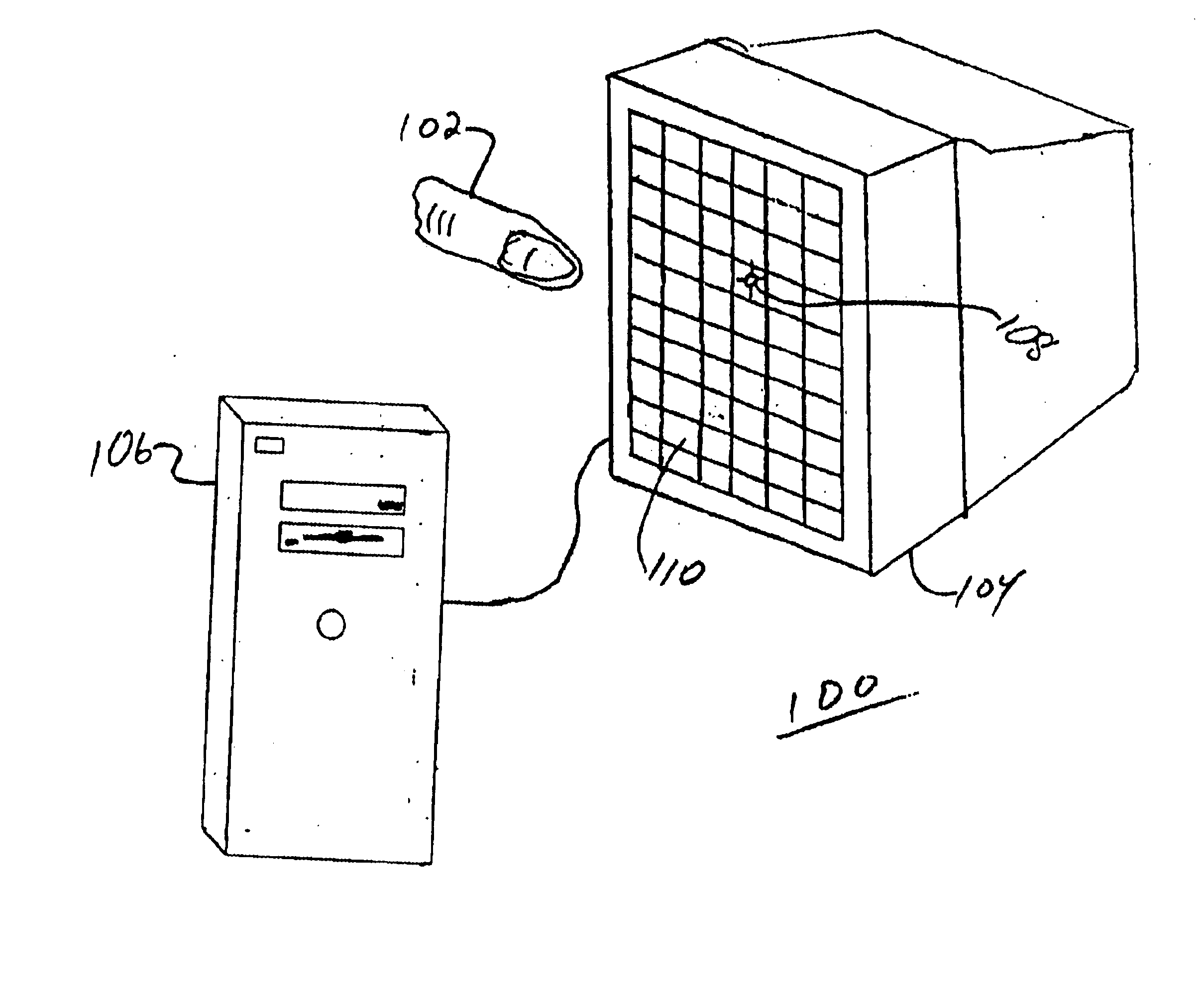
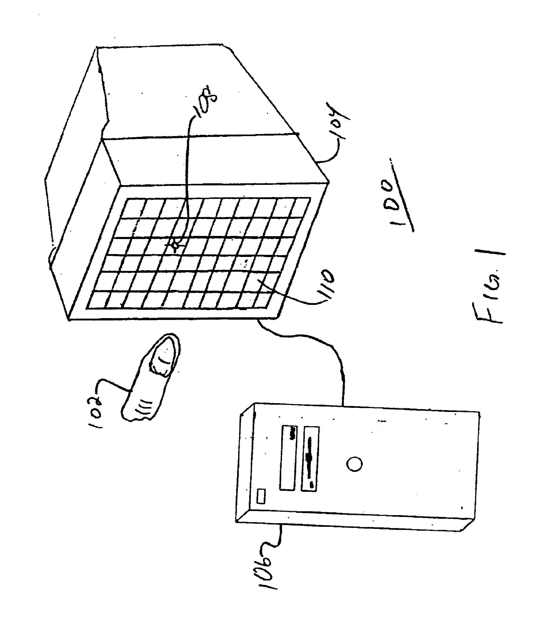
Turning now to the drawings and more particularly, FIG. 1 shows a three dimensional (3-D) Interactive Display System 100 according to the present invention. An operator probe 102 is shown directed at a 3D interactive display 104. The probe 102 may be a stylus, a finger, a point on a hand or any other appropriate object. The type and shape of the probe 102 may be selected as appropriate for the particular application being executed and displayed and for the desired computer response.

The display 104 of the present invention includes a transparent capacitor (TC) camera 110 (represented as a grid) covering the face of a computer monitor. In addition to the display 104, the computer monitor includes interface circuits (not shown) connecting both the TC Camera 110 and the monitor to a computer 106. Accordingly, a computer-driven signal processor (not shown) is included to interpret signals from the TC camera 110 and provide interpreted signal results to the computer 106 which, in turn, in...


PUM

PropertyMeasurementUnit
thickaaaaaaaaaa
length/widthaaaaaaaaaa
transparentaaaaaaaaaa

Abstract

A three-dimensional (3-D) interactive display and method of forming the same, includes a transparent capaciflector (TC) camera formed on a transparent shield layer on the screen surface. A first dielectric layer is formed on the shield layer. A first wire layer is formed on the first dielectric layer. A second dielectric layer is formed on the first wire layer. A second wire layer is formed on the second dielectric layer. Wires on the first wire layer and second wire layer are grouped into groups of parallel wires with a turnaround at one end of each group and a sensor pad at the opposite end. An operational amplifier is connected to each of the sensor pads and the shield pad biases the pads and receives a signal from connected sensor pads in response to intrusion of a probe. The signal is proportional to probe location with respect to the monitor screen.

Description

ORIGIN OF INVENTIONThe inventor of the invention described herein is an employee of the United States Government. Therefore, the invention may be manufactured and used by or for the Government for governmental purposes without the payment of any royalties thereon or therefor.BACKGROUND OF THE INVENTION1. Technical Field of the InventionThis invention generally relates to data input devices and more particularly to an apparatus, for a manual input device manually providing three dimensional input to a computer.2. Description of Related ArtU.S. Pat. No. 5,373,245 ('245) entitled “Capaciflector Camera” to John M. Vranish, which is incorporated herein by reference, teaches a capacitive type proximity sensor having an improved range and sensitivity between the sensor surface and an intruding object in the vicinity of that surface. The capaciflector camera described therein includes sensors and a shield that are strips of conductive material with an insulator coating. These strips of cond...

Claims


Application Information

Patent Timeline
Patent Type & Authority Patents(United States)
IPC IPC(8): G06F3/033G06F3/00G06F3/01G06F3/044
CPCG06F3/044G06F2203/04101G06F3/0445G06F3/0446
Inventor VRANISH, JOHN M.
Owner NASA
Why Eureka
Try Eureka