

Dual-mode tilting/swinging roof window
A dual-mode, roof window technology, applied in door/window accessories, roof, roof cladding, etc., can solve the problem of loss of rigidity and stability of the window element system
- Summary
- Abstract
- Description
- Claims
- Application Information
AI Technical Summary
Problems solved by technology
Method used
Image

Examples
Embodiment A
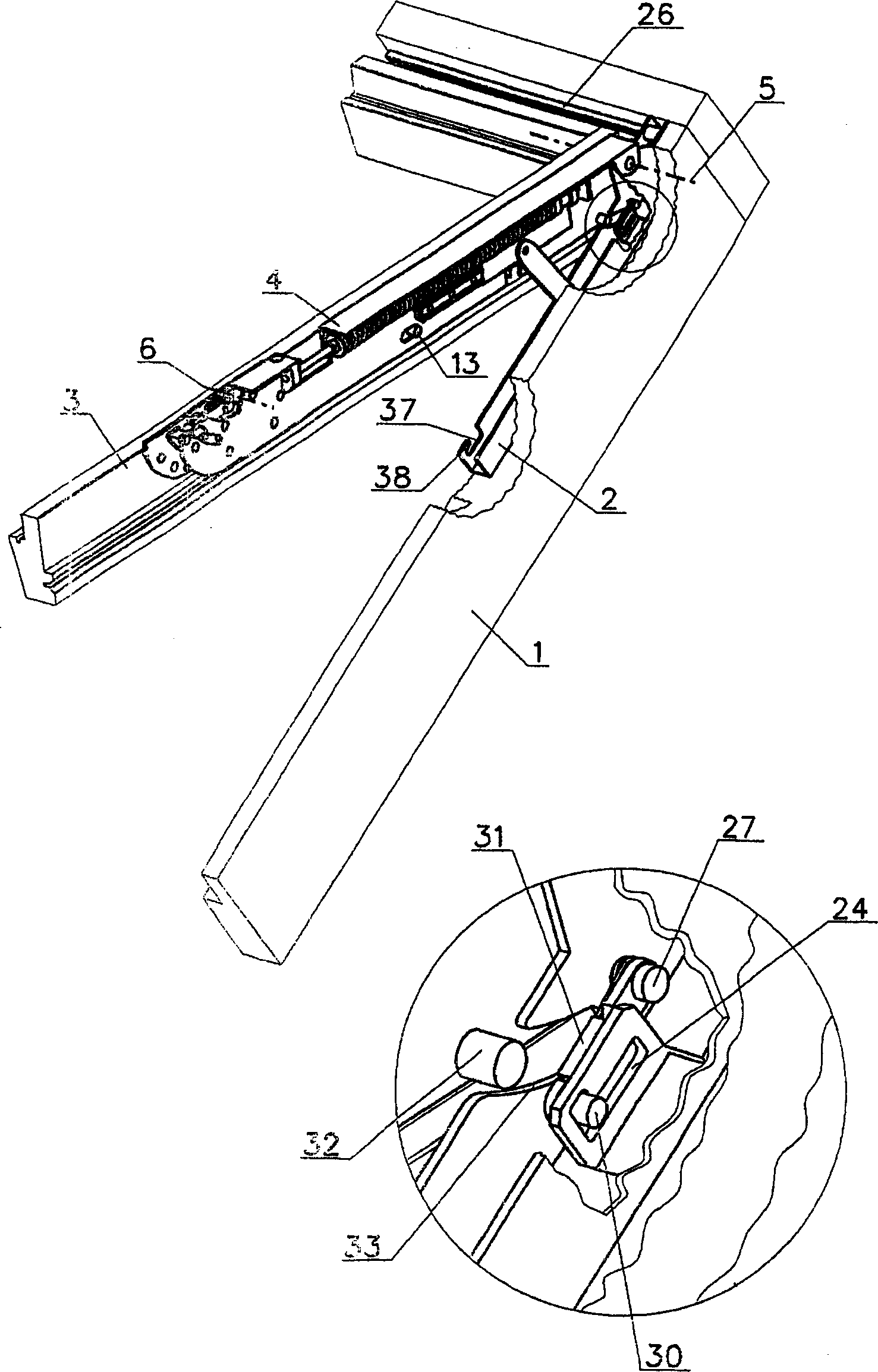
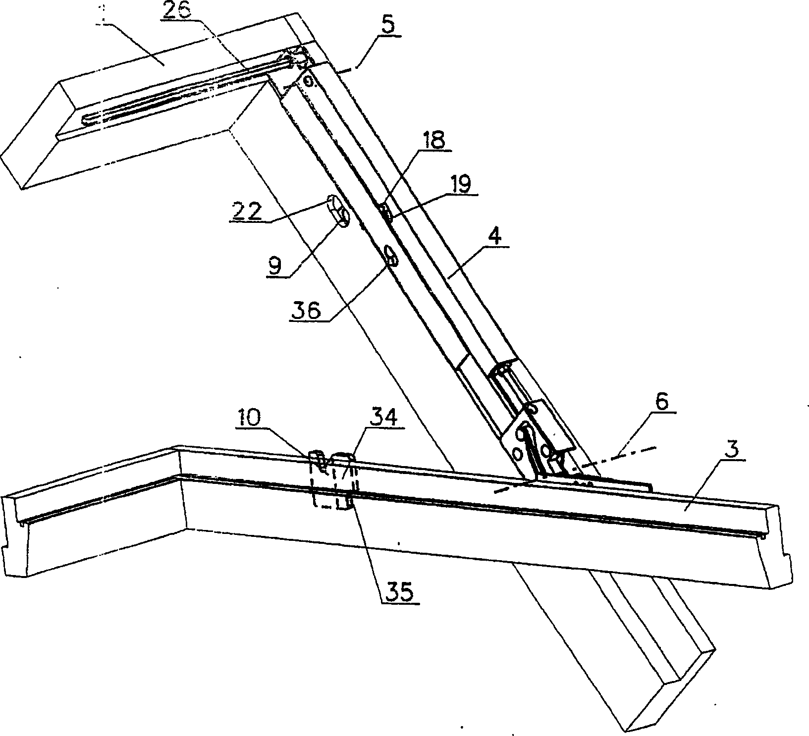
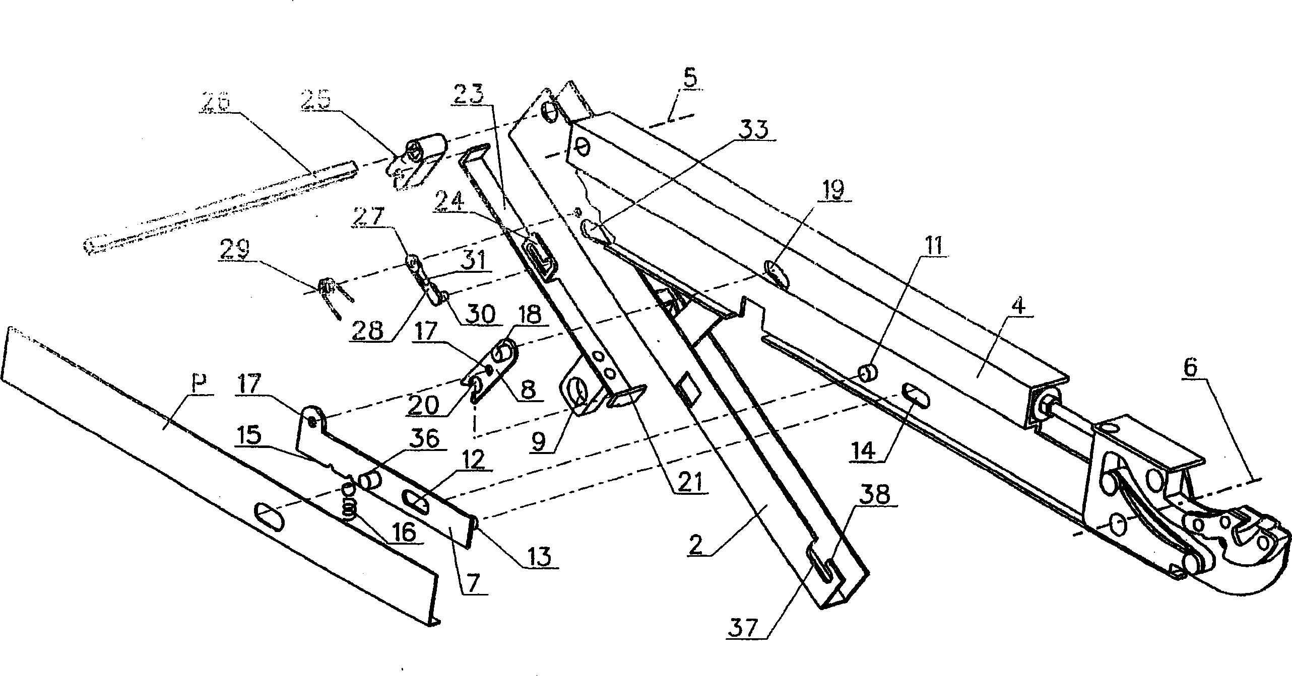
[0012] A dual-mode tilt / swing roof window has a window frame 1 with fittings 2 along its side pieces, and a window frame 3 connected on both sides by intermediate arms 4 .
[0013] The sash 3 is pivotally connected to the opposite end of the intermediate arm 4, and the swing pivot 6 is positioned in the middle of the height of the sash 3. When the window is in the closed position, the intermediate arm 4 is positioned between the window frame 1 and the side parts of the window frame 3 . The windows are provided with a locking system including two capture systems and a control system.
[0014] The control mechanism of the locking system includes a bar 7 connected with a rocker 8 , a switch 9 with a wedge-shaped recess and a support 10 . The strip 7 is arranged in the intermediate arm 4 so that said strip 7 can slide along said intermediate arm 4 and its transmission is limited by the pin 11 on the intermediate arm and in the intermediate arm 4 with the oval ( The opening 14 of...
Embodiment B
[0025]A dual-mode tilt / swing roof window has a window frame 1 with fittings 2 along its side pieces, and a window frame 3 connected on both sides by intermediate arms 4 . The intermediate arm 4 is pivotably connected at one end with the fitting 2 relative to an inclined pivot 5 positioned close to the upper part of the window frame 1 . The window frame 3 is pivotably connected to the other end of the intermediate arm 4 , and the swing pivot 6 is positioned in the middle of the height of the window frame 3 . In the window closed position, the intermediate arm 4 is positioned between the window frame 1 and the side parts of the window frame 3 .
[0026] The control mechanism of the locking system comprising a strip 7 connected by a spring 40 and a striplet 39 and also a wedge element 41 is provided in the side part of the sash 3 with the wedge surface oriented towards the tilting pivot 5 . The strip 7 with the catch in its middle part and the thrust element 43 at the end locate...
Embodiment C
[0038] A dual-mode tilt / swing roof window has a window frame 1 with fittings 2 along its side pieces, and a window frame 3 connected on both sides by intermediate arms 4 . The intermediate arms 4 are connected at one end with the fittings 2 so that they can rotate about a tilt pivot 5 positioned close to the upper part of the window frame 1 . The sash 3 is pivotally connected to the opposite end of the intermediate arm 4 , and the swing pivot 6 is positioned in the middle of the sash 3 . When the window is in the closed position, the intermediate arm 4 is positioned between the window frame 1 and the side parts of the window frame 3 .
[0039] The control mechanism of the locking system is provided in the intermediate arm 4, said control mechanism comprising the strip 7 and the small strip 39 connected by a spring 40, and also a wedge-shaped element 41 provided in the side part of the window frame 3, wedge-shaped The surface is oriented towards the swing pivot 6 and also incl...
PUM
 Abstract
Description
Claims
Application Information