

An electric knife sharpener
A knife sharpener and electric technology, applied in other manufacturing equipment/tools, manufacturing tools, etc., can solve laborious and time-consuming problems
- Summary
- Abstract
- Description
- Claims
- Application Information
AI Technical Summary
Problems solved by technology
Method used
Image

Examples
Embodiment Construction
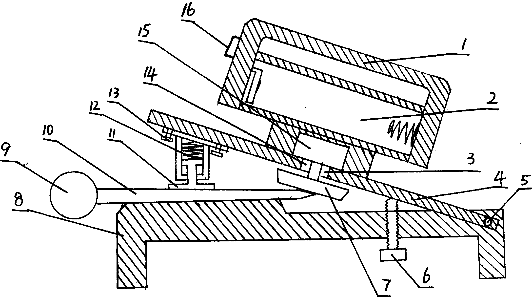
[0008] from figure 1 Visible, the present invention comprises platen 8 and angle adjustment plate 4, and the right end of angle adjustment plate 4 and the right end of platen are pinned together with pin bar 5, and pin bar 5 constitutes the rotation axis of angle adjustment plate 4, and the center of angle adjustment plate An electric box 1 is fixed on the top, and a battery switch 16 is installed on the electric box. There is a battery box 2 in the electric box and a motor 15 is fixed between the battery box and the angle setting plate. The shaft 14 of the motor 15 has a bearing 3 and passes through the angle adjustment plate. 4. The lower end of the motor shaft 14 is equipped with a grinding wheel piece 7, and the angle adjustment bolt 6 is screwed on the right part of the platen 8 through the platen 8 from the bottom up, and the lower surface of the left end of the angle adjustment plate 4 is installed downward with a pressing knife surface spring telescopic column. When s...
PUM
 Abstract
Description
Claims
Application Information