A valve for a drinking receptacle

A drinking container and valve seat technology, applied in the field of low pressure start-up and outflow mechanism, can solve the problems of valve surface damage, strong deformation, increased cost and complexity, etc.

Inactive Publication Date: 2006-12-20
SMARTSEAL AS
View PDF2 Cites 6 Cited by
  • Summary
  • Abstract
  • Description
  • Claims
  • Application Information

AI Technical Summary

Problems solved by technology

Often, the valve surface can also be damaged during assembly as it becomes strongly deformed when forces are applied through the valve opening
Added cost and complexity using currently available methods for inspecting the surface

Method used


Image

  • A valve for a drinking receptacle
  • A valve for a drinking receptacle
  • A valve for a drinking receptacle

Examples


Embodiment Construction

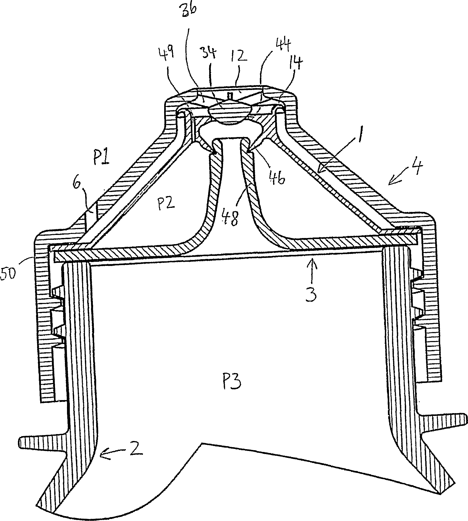
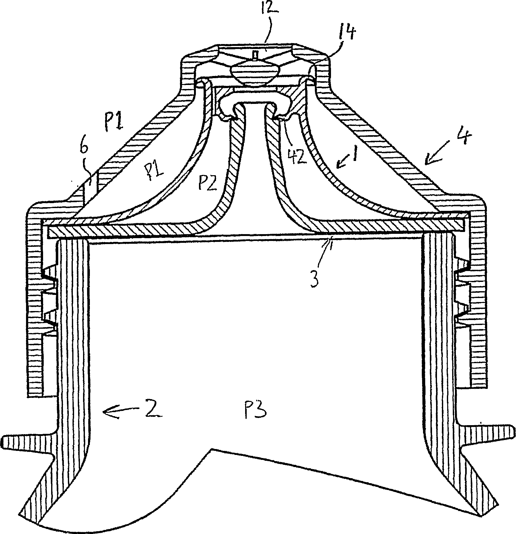
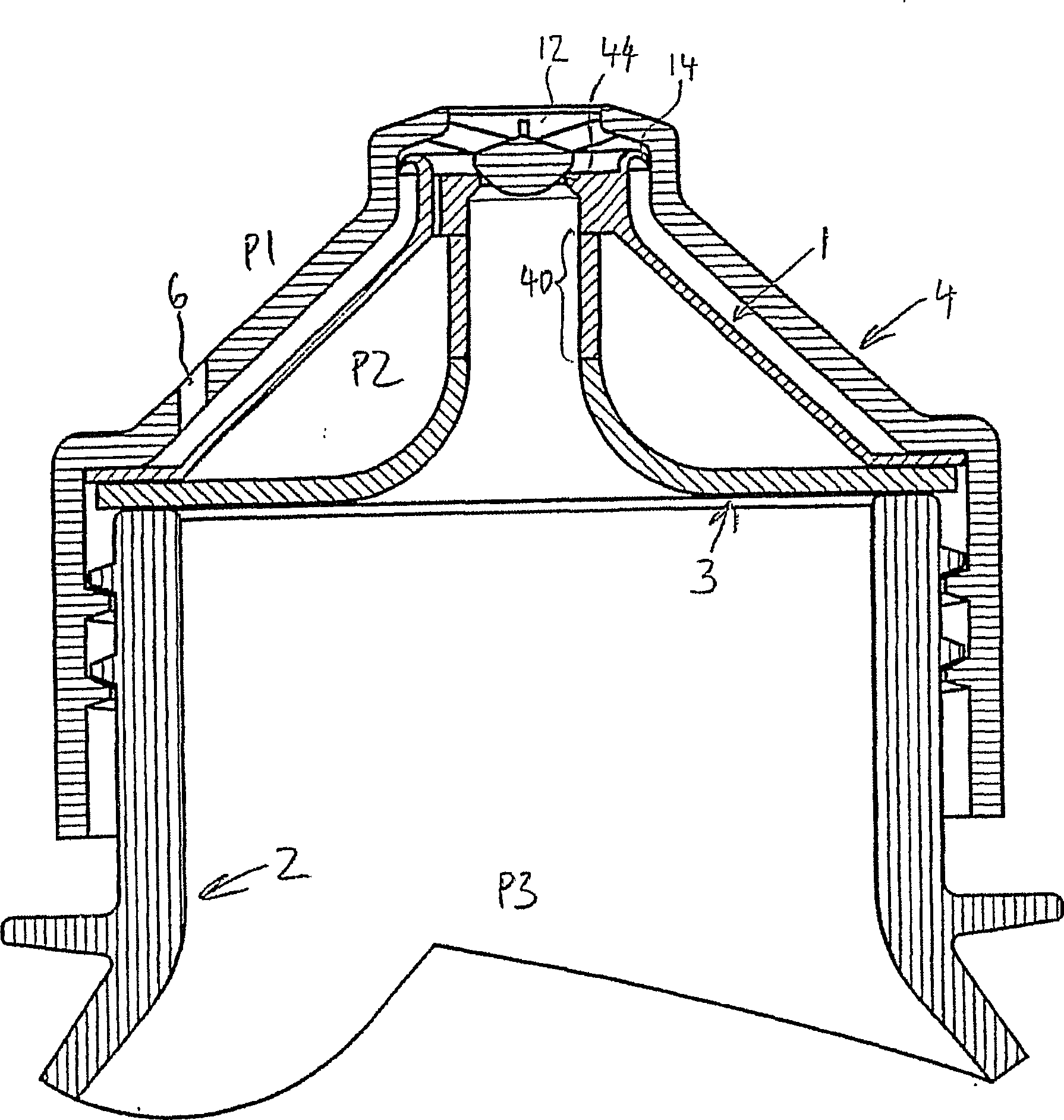
[0014] Figure 1a An embodiment of a valve device according to the invention is shown wherein said device is connected to a drinking container 2, in this example a bottle. In its rest position, the valve seat 44 will be in pressure-tight contact with the valve head 34 . The valve head 34 is secured within the cover and / or to the remainder by one or more stays 36 . When a low pressure P2 is applied to the inside of the membrane 1 through the suction channel 49, the radial shape of the membrane 1 changes and becomes shorter axially. As the membrane 1 is secured at its lower end 50, the resulting suction force moves the valve seat 44 away from the valve head 34, which is downwards in the drawing, and opens the valve for outflow. The seal 46 is also connected in a pressure-tight manner to the valve seat 44 and is directed towards the drinking container 2 against a projecting, tubular channel 48 on the pressure-tight partition 3 . A movable and / or flexible flange 14 in pressure-...


PUM


Abstract

This invention concerns a valve for an underpressure-activated outflow mechanism for a drinking receptacle (2). The valve includes a valve head (34) and a valve seat (44), in which the valve seat (44) is arranged in force-transmitting connection with a membrane (1), whereas the valve head (34) is fixed to the remaining structure via at least one stay (36).

Description

technical field [0001] The invention relates to low pressure activated outflow mechanisms in valves for drinking vessels. The valve comprises a valve head and a valve seat, the valve seat being arranged in force connection with the membrane, and the valve head being fixed to the rest of the structure. Background technique [0002] The patent literature discloses several devices using low pressure to actuate valves for drinking containers, for example as shown in US Patent No. 6,290,090 and Norwegian Patent No. 315182. All prior art in this field is that the valve seat is fixed to the structure, only the sealing surface of the valve head can be moved or change shape during actuation. First and foremost, the present invention seeks to improve the cost of manufacture and related aspects of the prior art. Having the valve seat movable makes it possible to avoid the need for the valve head to require a horizontal sealing surface which, after molding, must be pulled out of the c...

Claims


Application Information

Patent Timeline
Patent Type & Authority Applications(China)
IPC IPC(8): B65D47/20
CPCB65D47/2081Y10T137/7722
Inventor 谢蒂尔·内斯杰
Owner SMARTSEAL AS
Why Eureka
Try Eureka