Right-angle type pneumatic valve based on pilot structure

A right-angle, pneumatic valve technology, applied in the valve shell structure, the device used to relieve pressure on the sealing surface, the lift valve, etc., can solve the problems of slow speed, large opening torque, etc., to improve the service life and reduce the opening Powerful, easy-to-operate effects

Inactive Publication Date: 2015-12-16
UNIV OF JINAN
View PDF5 Cites 0 Cited by
  • Summary
  • Abstract
  • Description
  • Claims
  • Application Information

AI Technical Summary

Problems solved by technology

[0004] The patent of the present invention provides a right-angle pneumatic valve based on the pilot structure to solve the problems of large opening torque and slow speed in the above-mentioned background technology

Method used


Image

  • Right-angle type pneumatic valve based on pilot structure
  • Right-angle type pneumatic valve based on pilot structure
  • Right-angle type pneumatic valve based on pilot structure

Examples


Embodiment

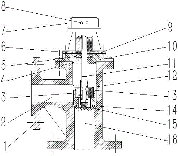
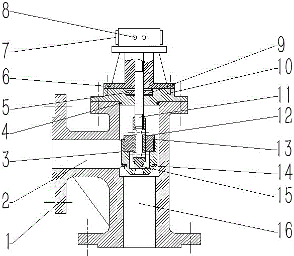
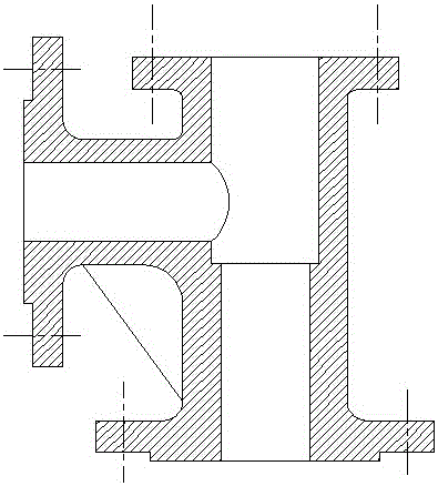
[0039] Such as figure 1 , figure 2 , image 3 As shown, this embodiment includes a valve body 1, a material inlet 2, a valve core 3, a valve cover sealing ring 4, a pressure plate 5, a support frame 6, a rotary cylinder 7, control buttons 8, a pilot rod sealing ring 9, and a valve cover 10. Pilot rod 11, spool closing plug 12, spool sealing plug sealing ring 13, spool sealing ring 14, pilot spool 15, discharge port 16; valve body 1 is fixedly installed with bonnet 10, bonnet 10 top is fixedly installed and is provided with support frame 6, and is fixedly installed on support frame 6 and is provided with rotary cylinder 7, and is fixedly installed on rotary cylinder 7 and is provided with control button 8, and support frame 6 interior is connected with pilot rod 11 threads, and pilot rod 11 upper ends are connected with The rotary cylinder 7 is fixedly connected; the pilot rod 11 is cooperating with the valve cover 10 and is provided with a pressure plate 5, and the other e...


PUM


Abstract

The invention belongs to the technical field of valve equipment, and particularly relates to a right-angle type pneumatic valve based on a pilot structure. The right-angle type pneumatic valve based on the pilot structure comprises a valve body. A valve deck is fixedly installed on the upper portion of the valve body. A supporting frame is fixedly installed on the upper portion of the valve deck. A rotary air cylinder is fixedly installed on the supporting frame. A control press key is fixedly installed on the rotary air cylinder. The interior of the supporting frame is in threaded connection with a pilot rod, and the upper end of the pilot rod is fixedly connected with the rotary air cylinder. The pilot rod and the valve deck are provided with a pressing plate in a matched mode, the other end of the pilot rod is in threaded connection with a pilot valve element, a valve element sealing plug is installed outside the pilot valve element in a matched mode, and the outside of the valve element sealing plug is in threaded connection with a valve element. The side, far away from the valve element, of the valve body is provided with a feeding inlet, and a discharging outlet is formed below the valve element. The right-angle type pneumatic valve adopts a pilot structure, is capable of being opened rapidly, is small in opening torsion and largely prolongs the service life.

Description

technical field [0001] The patent of the invention belongs to the technical field of valve equipment, and in particular relates to a right-angle pneumatic valve based on a pilot structure. Background technique [0002] Valves are used in fluid systems to control the direction of fluid, pressure 1. The flow device is a device that makes the medium (liquid, gas, powder) in the piping and equipment flow or stops and can control its flow. The control of the valve can adopt a variety of transmission methods, such as manual, electric, hydraulic, pneumatic, turbine, electromagnetic, electro-hydraulic, electro-hydraulic, gas-hydraulic, spur gear, bevel gear drive, etc.; can be driven by pressure, temperature Under the action of sensing signals in other forms, it acts according to predetermined requirements, or simply opens or closes without relying on sensing signals. The valve relies on driving or automatic mechanism to make the opening and closing parts lift, slide, swing or rota...

Claims


Application Information

Patent Timeline
IPC IPC(8): F16K1/04F16K1/36F16K1/38F16K1/46F16K27/08F16K39/02F16K41/02
CPCF16K1/04F16K1/36F16K1/38F16K1/46F16K27/08F16K39/024F16K41/02
Inventor 昃向博张孟杰陈泽榕
Owner UNIV OF JINAN
Why Eureka
Try Eureka