
Thermospray feeding-flame atomizer for atomic spectrometry

A technology of atomizer and atomic spectrum, which is applied in the field of atomic spectrum analysis and testing, and can solve the problem of low detection ability

Inactive Publication Date: 2006-12-27
SICHUAN UNIV
View PDF0 Cites 0 Cited by
  • Summary
  • Abstract
  • Description
  • Claims
  • Application Information

AI Technical Summary

Problems solved by technology

[0004] The purpose of this invention is to propose a new flame atomizer, to overcome the low defect of existing flame atomic absorption spectrometry detection ability,

Method used


Image

  • Thermospray feeding-flame atomizer for atomic spectrometry

Examples


Embodiment

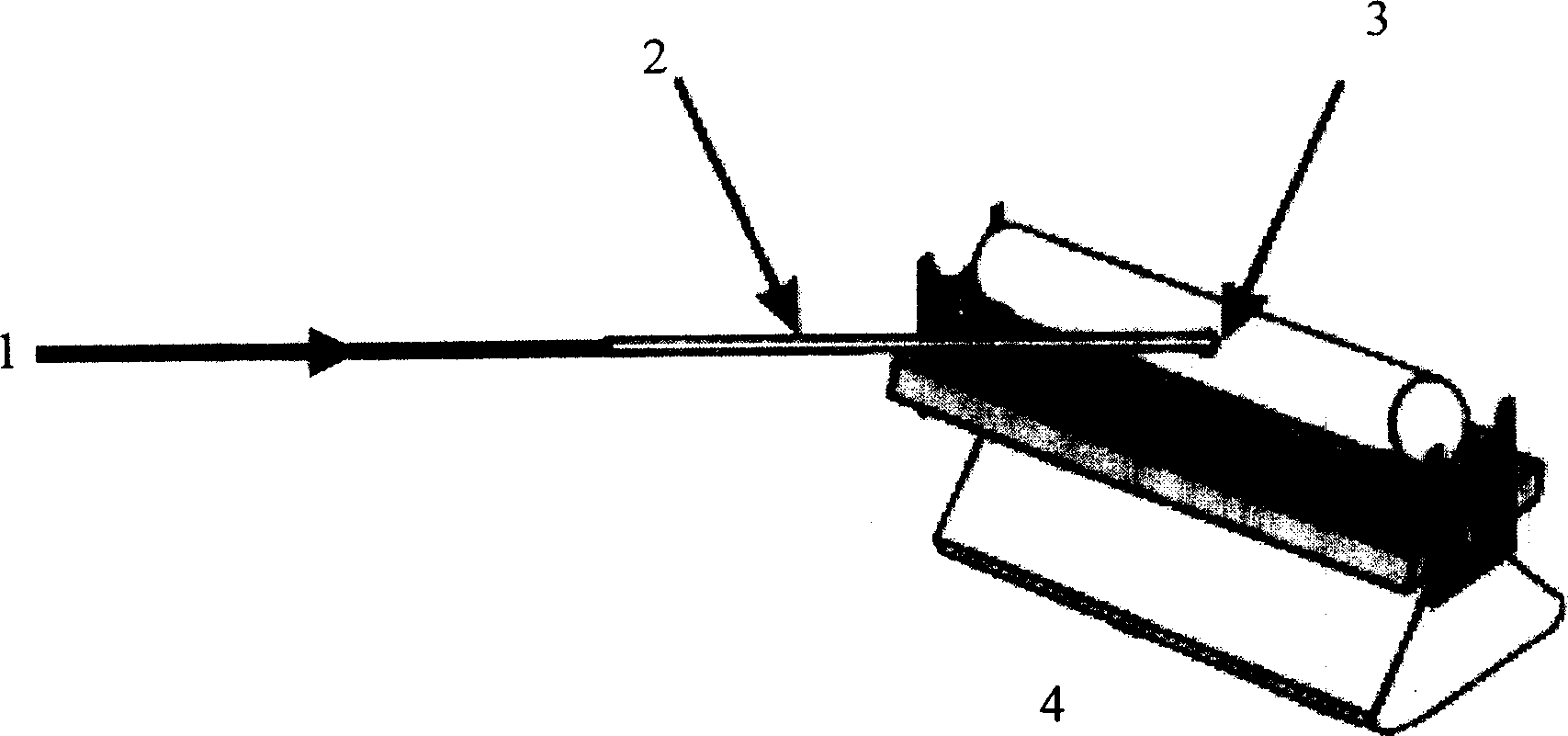
[0008] The example that the present invention is used for flame atomic absorption is as follows: first ignite the air-acetylene flame of flame atomic absorption instrument during work, flame furnace 3 (instrument figure is shown in the accompanying drawing of specification sheet) is placed on the stainless steel support on the combustion head 4, then Insert the thermal spray capillary 2 horizontally and vertically into the flame furnace. The sample solution 1 is lifted into the pipeline by the pump and enters the thermal spray capillary through the connector to be thermally atomized. The sample aerosol enters the flame furnace 3 at high speed and is atomized. The free atomic absorption light signal in the flame furnace is detected by the flame atomic absorption instrument. The software records, thus completes the working process of the present invention. See Table 1 for the detection limits of some elements when the present invention is applied to flame atomic absorption.

[...


PUM


Abstract

The invention is sued in the hot spray sampling-fire furnace atomizing device of atom spectrum analysis, wherein it combines the hot spray sampling method and the fire furnace atomizing device, to improve the sensitivity of fire atom adsorption of traditional atom spectrum analysis. Compared with present air-powered spraying method, the invention has high utilization and low amount of sample; the invention can prolong the time of free atom stay in the light path, to improve the test sensitivity.

Description

1. Technical field: [0001] The invention belongs to the technical field of atomic spectrum analysis and testing, and relates to the design of a flame furnace atomizer and a thermal spray sampling device, and the proposal of a new analysis method of thermal spray sampling-flame furnace atomic absorption spectroscopic analysis. 2. Background technology: [0002] Flame atomic absorption spectrometry (Flame atomic absorption spectrometry, FAAS) has been playing an important role in trace element analysis due to its simplicity and speed, but its relatively low detection limits its application range. There are two main reasons for the low sensitivity of FAAS: 1. Pneumatic nebulization is generally used for sample injection in flame atomic absorption, and its sample injection efficiency is lower than 10%; 2. Flame atomizer is an open system, and free atoms are in the optical path. The dwell time is very short (2-5ms). In addition, the atomization efficiency of some elements in the...

Claims


Application Information

Patent Timeline
IPC IPC(8): G01N21/31G01N21/00
Inventor 侯贤灯吕弋吴鹏张云嫦
Owner SICHUAN UNIV
Learn More