Fitting structure for built in type apparatus

A technology of appliance and structure, which is applied in the field of installation and structure of embedded appliances, can solve problems such as the inability to set the roof, damage to the ceiling lamp, etc., and achieve the effect of preventing damage

Inactive Publication Date: 2007-01-10
ENDO LIGHTING CORP
View PDF2 Cites 5 Cited by
  • Summary
  • Abstract
  • Description
  • Claims
  • Application Information

AI Technical Summary

Problems solved by technology

[0015] However, since the installation metal parts erected toward the top of the installation frame are complex and bulky, there is a problem that sufficient installation space is required inside the roof and cannot be installed in a narrow space inside the roof.
In additi

Method used


Image

  • Fitting structure for built in type apparatus
  • Fitting structure for built in type apparatus
  • Fitting structure for built in type apparatus

Examples


Embodiment 2

[0072] 4( a ), ( b ) are enlarged side views showing other embodiments of the support portion 13 according to the present invention.

[0073] And, with figure 1 The components that are the same as those shown in FIG. 3 are given the same reference numerals, and their introductions are omitted. At this time, only the features of the various embodiments are introduced.

[0074] The supporting part 13 shown in Fig. 4(a) further extends downward the claw part 13d after extending the upper end of the guide inclined surface 13c to the outside to form a detachment preventing part 13d'.

[0075] If the detachment preventing portion 13d' is formed, the engaging portion 23b guided by the guide inclined surface 13c and engaged with the contact claw portion 13d is more reliably engaged and can be prevented from being detached.

[0076] In the support portion 13 shown in FIG. 4( b ), the claw portion 13d formed on the support portion 13 is formed as a long hole with the same inclination a...

Embodiment 3

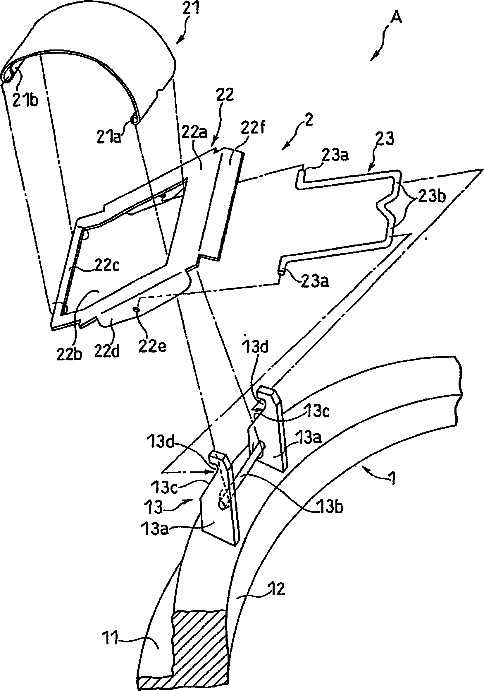
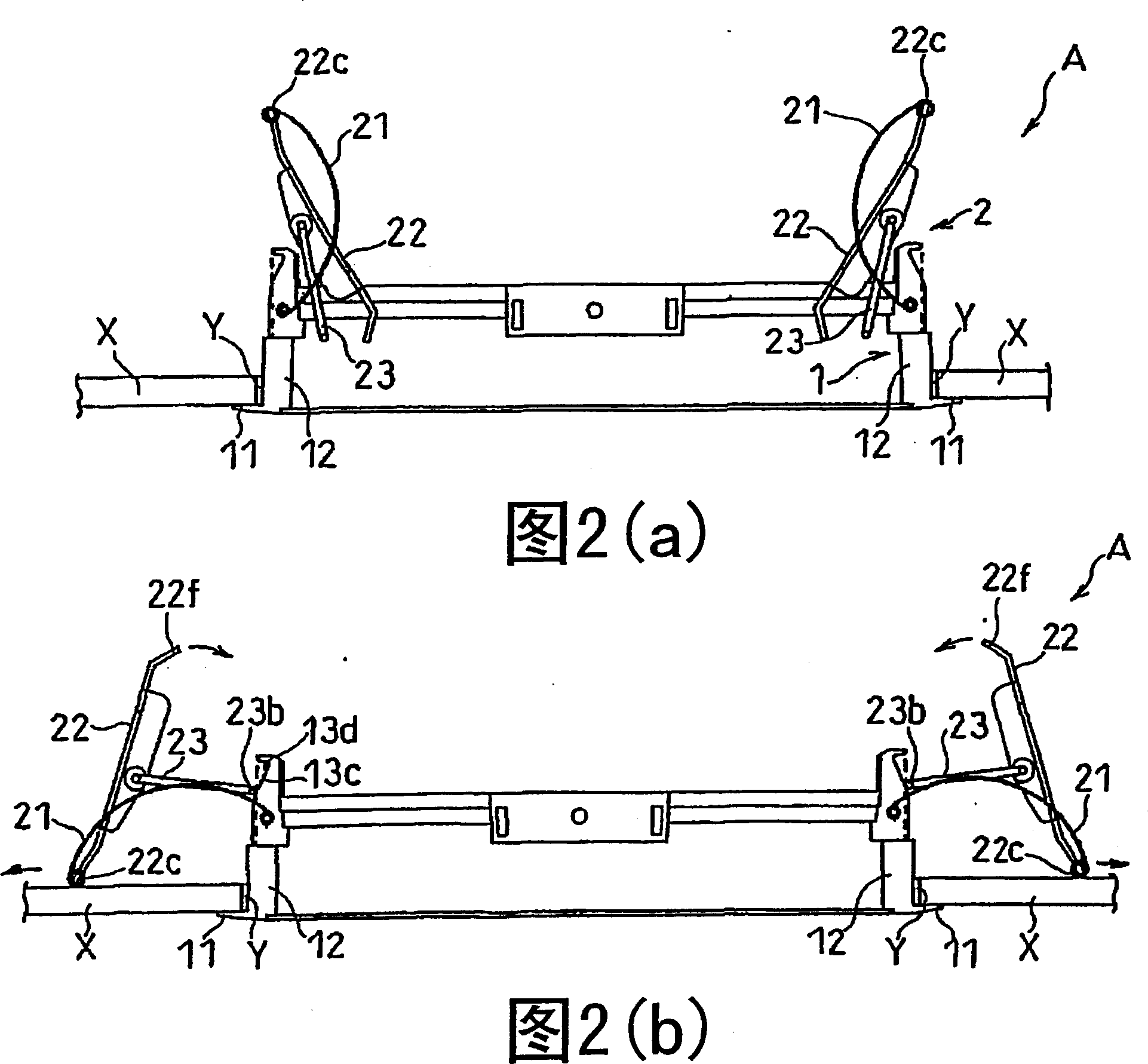
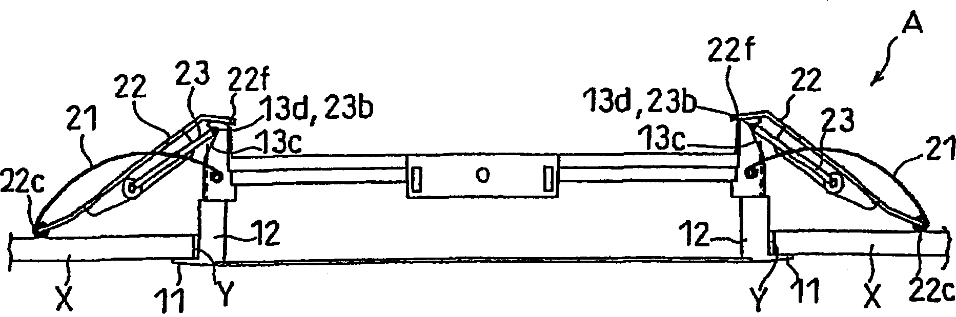
[0079] Figure 5 It is a perspective view showing the key parts of yet another embodiment of the installation structure A of the embedded appliance of the present invention, and FIG. 6 shows Figure 5 An explanatory diagram of the installation operation of the installation structure A of the embedded appliance shown.

[0080] And, with figure 1 The components that are the same as those shown in FIG. 4 are given the same reference numerals, and their introductions are omitted, and only the features of the various embodiments are introduced at this time.

[0081] The mounting structure A of this embedded appliance is characterized in that both ends 23c are pivotally supported on the flap portion 22d formed by bending both sides of the base plate 22a of the operation piece 22, and the front is penetrated to the support portion of the mounting frame 1. A set of ring-shaped toggle levers 23 formed by the shaft holes 13e on the 13;

[0082] That is, the toggle link 23 shown in th...


PUM


Abstract

The present invention is an installation structure for embedded appliances, which is used to accommodate and fix the installation frame of the installation appliance body in the installation hole formed on the ceiling, wall, etc., the installation frame has a frame frame embedded in the installation hole, formed The frame frame has a flange piece extending out of the mounting hole, and the support portion is connected to the mounting parts, and each mounting part is equipped with a leaf spring, an operating piece with an opening, One end is pivotally supported on the operating piece and the other end has a toggle lever with an engaging end, the leaf spring passes through the opening of the operating piece, one end is pivotally supported on a support shaft provided on the supporting portion, and the other end is pivotally supported on On the operation piece, after inserting the installation frame into the installation hole, abut one end of the operation piece against the inside of the top plate, wall, etc., and elastically deform the leaf spring to engage the engaging end with the claw of the support part of the installation frame part, whereby the mounting frame is lifted by the elastic force of the leaf spring.

Description

technical field [0001] The present invention relates to an installation structure of a built-in appliance in which an appliance body is embedded in a mounting hole formed on a ceiling, a wall, etc., and the appliance body is mounted on a ceiling, a wall, or the like. Background technique [0002] Conventionally, as an attachment structure in which a fixture main body is embedded in an attachment hole formed in a ceiling, for example, an attachment structure of a lighting fixture such as a downlight is known. Hereinafter, in this specification, this downlight will be described as a representative example, but other installation structures can also be used, for example, installation of audio equipment such as speakers buried in installation holes opened on ceilings, walls, etc. structure etc. [0003] As the installation structure of the conventional downlight, there is a so-called screw-fixed installation structure, which is buried in the installation hole formed in the ceil...

Claims


Application Information

Patent Timeline
IPC IPC(8): F21V21/04
Inventor 藤本佳史
Owner ENDO LIGHTING CORP
Why Eureka
Try Eureka