Method of manufacturing mounting board with reflector

A manufacturing method and technology of mirrors, which are applied in semiconductor/solid-state device manufacturing, electrical components, electrical solid-state devices, etc., can solve the problems of mirror deformation, defective products, inability to increase the effective utilization rate, etc., and achieve a narrower interval. Effect

Inactive Publication Date: 2007-01-10
ELEMENT DENSHI
View PDF2 Cites 0 Cited by
  • Summary
  • Abstract
  • Description
  • Claims
  • Application Information

AI Technical Summary

Problems solved by technology

[0009] Reflectors often use white resin with high light reflectance, so there is a problem that it is necessary to have a model for resin molding, which takes time for trial production.
[0010] In addition, since injection molding of thermoplastic resin is often used for resin molding, there is a problem that deformation such as warping occurs from high-temperature resin molding to removal from the mold.
Therefore, when the mirror is bonded to the mounting substrate, it is impossible to bond a plurality of mirrors to the mounting substrate at the same time due to the deflection.
[0011] Sin

Method used


Image

  • Method of manufacturing mounting board with reflector
  • Method of manufacturing mounting board with reflector
  • Method of manufacturing mounting board with reflector

Examples


Embodiment Construction

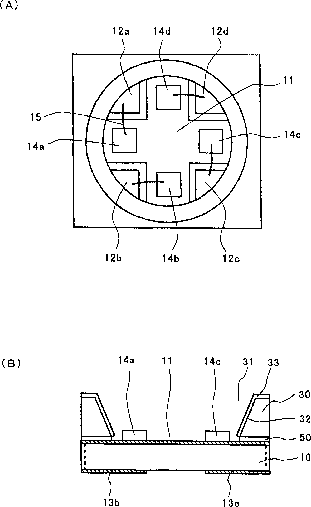
[0063] first, figure 1 A mirror mounted substrate completed by the manufacturing method of the present invention is shown. figure 1 (A) is the above picture, figure 1(B) is its cross-sectional view. Cross-shaped common electrodes 11 are provided on the mounting substrate, individual electrodes 12a, 12b, 12c, 12d are provided at the four corners, and lead-out electrodes 13a, 13b connected to corresponding electrodes through through-hole electrodes are provided below. On the upper side of the mounting substrate 10, the reflector 30 is pasted through the adhesive layer 50, so that a part of the common electrode 11 and the individual electrodes 12a, 12b, 12c, and 12d are exposed, and the inclined surface 32 and the upper surface of the through hole 31 of the reflector 30 are exposed. A reflective coating 33 is provided. Four light-emitting elements 14a, 14b, 14c, and 14d are respectively fixed on the cross protruding parts of the common electrode 11, and the common electrode...


PUM


Abstract

A method for fabricating a mounting board with an attached reflector is provided to embody a mounting board with a reflector by preparing a mounting board and a reflector board so that the boards are attached to each other by using adhesive. A plurality of electrodes for mounting a light emitting device are prepared. An inclined surface(32) is formed on the inner wall of a through hole(31) to surround each electrode for mounting the light emitting device, and a reflector board(34) is prepared in which a reflective plating layer is formed on the inclined surface of the through hole. The mounting board is attached to the reflector board by using an adhesive layer. The reflector board is made of a print board material capable of being mechanically processed. The through hole formed in the reflector board can be formed by mechanical processing.

Description

technical field [0001] The present invention relates to a manufacturing method of a mounting substrate with a reflecting mirror, and more particularly, to a method of manufacturing a mounting substrate with a reflecting mirror composed of a glass-epoxy resin substrate on which a light-emitting element is assembled. Background technique [0002] Figure 7 Indicates a light-emitting device with high luminous efficiency that effectively reflects light emitted from a light-emitting element to the side. [0003] This light-emitting device is composed of a light-emitting element 100 , a substrate 200 , a reflector 300 , and a sealing member 400 . The light emitting element 100 is a Group III nitride compound semiconductor light emitting element. The mounting substrate 200 is an insulating substrate, and a desired wiring pattern is formed on which the light emitting element 100 is mounted. The reflector 300 is made of polyamide resin in which titanium oxide is uniformly dispersed...

Claims


Application Information

Patent Timeline
IPC IPC(8): H01L21/00H01L33/00H01L33/60
CPCH01L2224/49107H01L2224/48091
Inventor 成田悟郎
Owner ELEMENT DENSHI
Why Eureka
Try Eureka