Vacuum pump, protection net, and contact component

A technology for contacting parts and vacuum pumps, which is applied in the direction of pump components, pumps, and parts of pumping devices for elastic fluids, etc. It can solve the problems of the decrease of the conductance of the vacuum pump 1 and the adverse effects of the exhaust performance of the vacuum pump 1, and achieve the goal of reducing the height Effect

Pending Publication Date: 2021-05-25
EDWARDS JAPAN
View PDF7 Cites 0 Cited by
  • Summary
  • Abstract
  • Description
  • Claims
  • Application Information

AI Technical Summary

Problems solved by technology

However, if the thickness of the protective net 100 is increased, there is a problem that the conductance of the vacuum pump 1 decreases, which adversely affects the exhaust performance of the vacuum pump 1.

Method used


Image

  • Vacuum pump, protection net, and contact component
  • Vacuum pump, protection net, and contact component
  • Vacuum pump, protection net, and contact component

Examples


Embodiment approach 1

[0077] (Embodiment 1: An embodiment in which the contact portion of the rotating body (shaft 7 or rotor 8) is formed into a shape with low resistance)

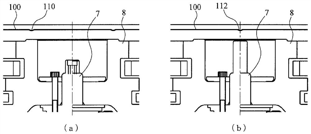
[0078] figure 2 It is a diagram for explaining an embodiment in which the contact portion of the shaft 7 with the protection net 100 is formed into a shape with low resistance.

[0079] exist figure 2 In the illustrated embodiment, the front end portion of the shaft 7 that contacts the shaft 7 when the protection net 100 is deformed is formed into a shape with low resistance, and the protection net 100 is supported to prevent entanglement.

[0080] exist figure 2 In (a), the front end portion 72 of the shaft 7 is spherical. exist figure 2 In (b), the front-end|tip part 74 of the shaft 7 is made into R chamfer shape.

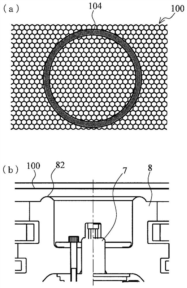
[0081] image 3 It is a diagram for explaining an embodiment in which the contact portion of the rotor 8 with the protective net 100 is formed into a shape with low resistance.

[0082] exist image 3...

Embodiment approach 2

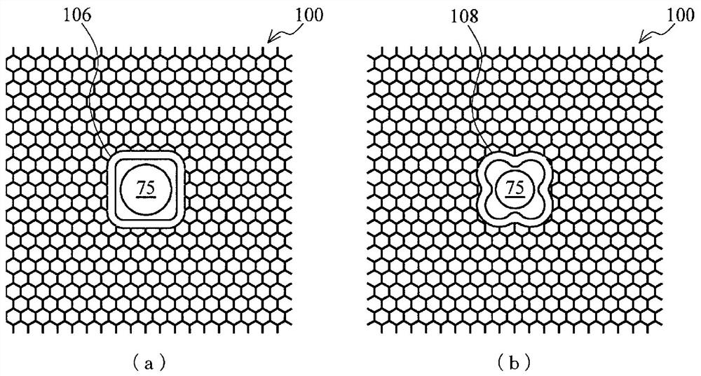
[0084] (Embodiment 2: An embodiment in which holes are opened in the protection net 100 and a shape is provided to contact and support a rotating body)

[0085] Figure 4 It is a diagram for explaining an embodiment in which holes are opened in the protection net 100 and a shape that is provided in contact with a rotating body and supported is provided.

[0086] In this embodiment, a hole is preliminarily drilled at the portion of the protection net 100 that contacts the protrusion 75 of the shaft 7 or the protrusion 85 of the rotor 8. If the protection net 100 deforms, the protrusion 75 of the shaft 7 or the rotor 8 The protrusions 85 immediately contact the holes of the protective net 100 to support the deformation of the protective net 100 .

[0087] Figure 4 (a) is a figure which shows the example which provided the tapered protrusion part 75 in the shaft 7, and made it contact the hole of the protection net 100, and supported it.

[0088] Figure 4 (b) is a diagram s...

Embodiment approach 3

[0099](Embodiment 3: In Embodiments 1 and 2, the contact portion (contact portion and protrusion) of the rotating body is configured with other components)

[0100] Figure 7 It is a figure explaining the embodiment which comprised the contact part (contact part) of the rotating body of Embodiment 1 and the contact part (protrusion part) of Embodiment 2 with another member.

[0101] Figure 7 (a) means that the figure 2 (a) is a diagram showing an example in which the tip portion 72 (formed integrally) of the shaft 7 according to Embodiment 1 is constituted by another member 78 .

[0102] Figure 7 (b) means that the Figure 4 (a) is a diagram showing an example in which the protruding portion 75 (formed integrally) of the shaft 7 according to the second embodiment is constituted by another member 79 .

[0103] Figure 7 (c) means that the image 3 (a) is a diagram showing an example in which the contact portion 82 (formed integrally) of the rotor 8 according to Embodi...


PUM


Abstract

Provided is a vacuum pump in which a rotor actively supports a protection net so as to minimize the interval between the rotor and the protection net, and which has a small height (length). A vacuum pump (1) according to an embodiment of the present invention is fitted, on the side of the rotor (a shaft (7) or a rotor (8)), with a mechanism for actively supporting a protection net (100) in the event of deformation (warping) of the protection net (100) toward the vacuum pump (1) due to changes in pressure or temperature, for example. That is, instead of preventing snagging by increasing the interval between the protection net (100) and the rotor, snagging is prevented by placing the protection net and the rotor closer to each other and actively supporting the protection net (100). Accordingly, the height (length) of the vacuum pump (1) can be reduced.

Description

technical field [0001] The present invention relates to a protective net provided at the suction port of a vacuum pump, and relates to providing a portion between the rotating body and the protective net to hold the protective net in contact with the rotating body and to prevent, for example, a large change in the internal pressure of the vacuum pump. Wait for the entanglement of the protective net caused by the rotating body. Background technique [0002] In a vacuum pump 1 such as a turbomolecular pump or a screw groove pump, a protective net 100 for preventing foreign matter from entering the vacuum pump 1 is provided on the side of the suction port 4 . [0003] Figure 16 It is a figure explaining this protection net 100 and the location where a protection net is installed in the air inlet 4. FIG. The protection net 100 has a shape in which many hexagonal holes are provided in a grid pattern, and the distance between the sides of the hexagons facing each other is about ...

Claims


Application Information

Patent Timeline
Patent Type & Authority Applications(China)
IPC IPC(8): F04D19/04F04D29/70
CPCF04D19/04F04D29/701F04D1/00F04D13/06F04C2220/10F04C2240/80F04C29/12F04C2230/91F04C2240/20
Inventor 山口俊树
Owner EDWARDS JAPAN
Why Eureka
Try Eureka