Cutting device

A cutting machine and workbench technology, applied in the field of cutting machines, can solve the problems of stagnation of sealing sheets, and achieve the effects of reducing the number of parts, simplifying manufacturing and reducing costs

Inactive Publication Date: 2009-03-25
SHIMA SEIKI MFG LTD
View PDF1 Cites 9 Cited by
  • Summary
  • Abstract
  • Description
  • Claims
  • Application Information

AI Technical Summary

Problems solved by technology

However, the cutting table 2 does not bear such a large load as the weight of a person like an escala

Method used


Image

  • Cutting device
  • Cutting device
  • Cutting device

Examples


Embodiment Construction

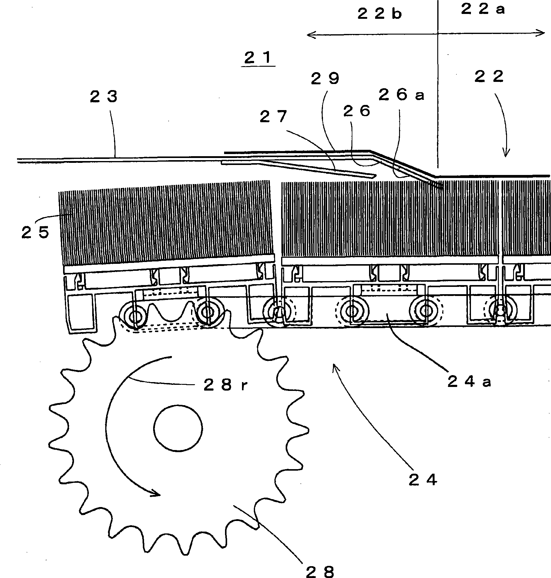
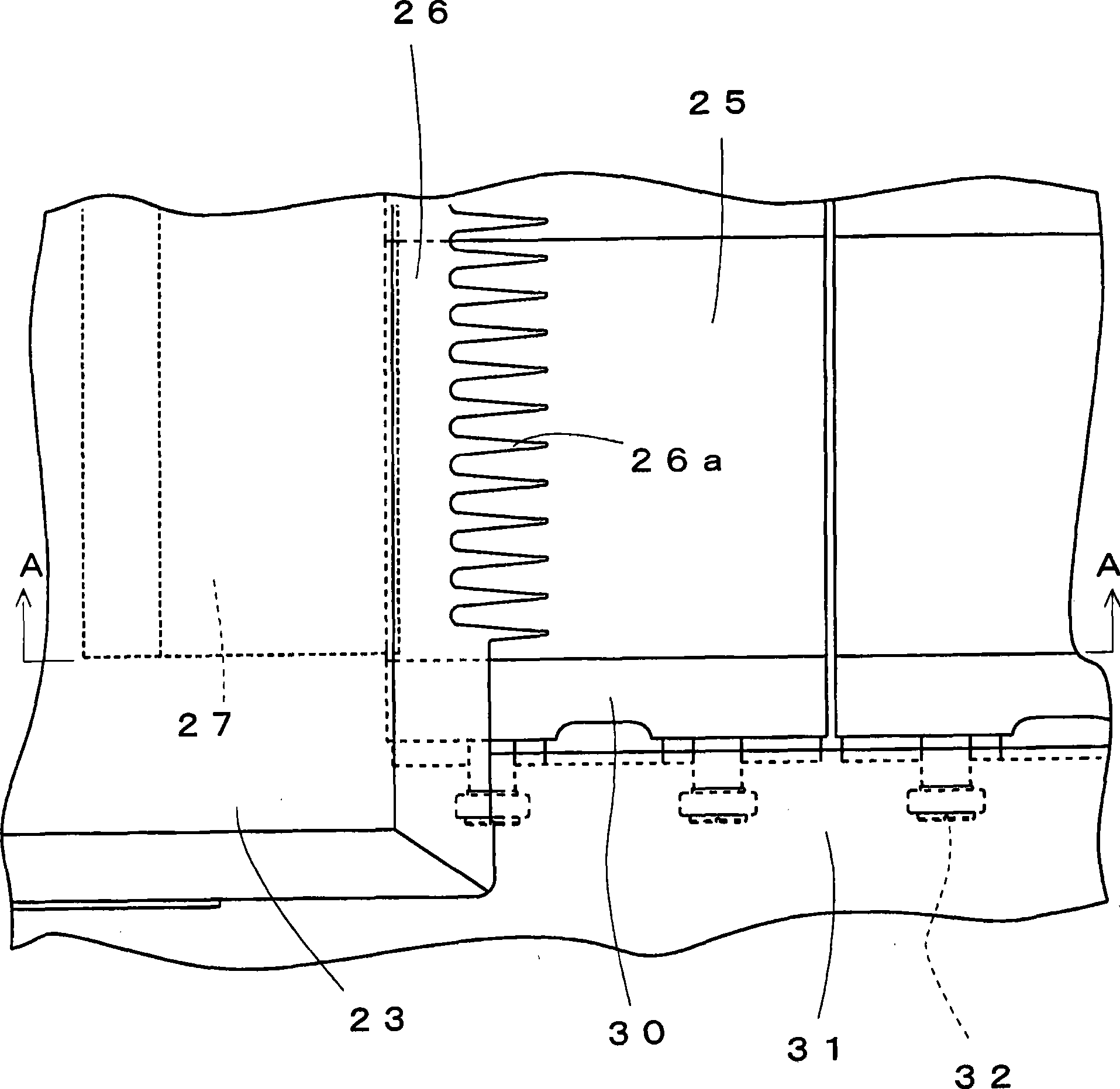
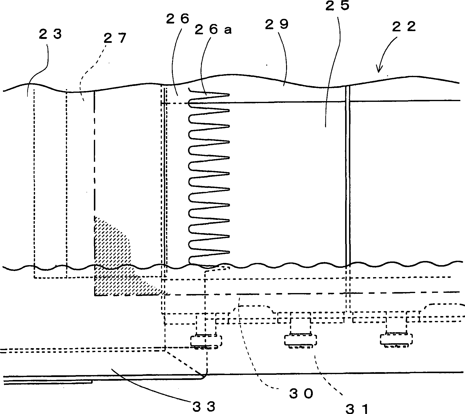
[0032] figure 1 It is the cutting machine 21 which is one embodiment of this invention, and the structure of the vicinity of the transfer part from the cutting table 22 to the carrying-out side wind table 23 is shown briefly. Carry out the side wind power workbench 23 and play the effect of taking out workbench. Regarding the structure of the cutting workbench 22, it is basically the same as the cutting machine of FIG. In the cutting machine 21, the guide plate 26 corresponding to the guide claw 16 of FIG. 5 is integrated with the carrying-out side wind table 23 using plate materials, such as a metal plate. That is, the front end side of the wind power table 23 on the bending delivery side is formed as an inclined part of the guide plate 26, and the further end of the guide plate 26 is formed in a comb-tooth shape as the guide claws 26a. The guide plate 26 can also be formed separately from the wind table 23 on the delivery side and then combined. However, the number of pa...


PUM


Abstract

The invention relates to a cutting machine in which a sealing strip can smoothly transfer from the cutting stage to the moving out side without stagnation caused by adsorption even when the sealing strip absorbs the cut slice material and transfers same at the same time. The front end of a wind power working stage (23) of a bending transfer side is used as an inclining portion of a guiding plate (26), the further front end of the guiding plate (26) is used as a guiding pawl (26a) and is formed to be a comb shape. The substrate end side of a shielding plate (27) is welded on the back side of wind power working stage (23) at the moving out side. The shielding plate (27) is fixed at a state that no unevenness is generated on the surface of the working stage (23) at the moving out side by welding. Since the shielding plate (27) exists, wind flow is attenuated, turbulence is formed, and absorption towards the sealing strip (29) near to the guiding pawl (26a) is attenuated, thereby preventing absorption.

Description

technical field [0001] The present invention relates to a cutting machine for cutting a sheet material such as cloth while attracting and holding it on a cutting table. Background technique [0002] At present, the production of parts for sewing clothes and the like is produced by cutting gray fabrics such as cloth according to paper patterns and the like. A trimmer is used for efficient trimming. [0003] FIG. 5 is a schematic configuration diagram of a conventional cutting machine 1 (for example, refer to Patent Document 1). The cutting table 2 of the cutting machine 1 is formed on the top surface of a substantially box-shaped frame 3 . The cutting table 2 forms part of the conveyor belt 4 . The surface of the conveyor belt 4 is formed with the tips of the bristles of the bristle brush 5 . The cutting head 6 moves along the surface of the cutting table 2, and the cutting blade 7 protrudes from the cutting head 6 toward the cutting table 2 side. In addition, a mechanis...

Claims


Application Information

Patent Timeline
IPC IPC(8): D06H7/00D06H7/06
Inventor 有北礼治味村郁夫
Owner SHIMA SEIKI MFG LTD
Why Eureka
Try Eureka