Ship encountering less frictional resistance

一种摩擦阻力、船舶的技术,应用在船舶推进、船体、船只部件等方向,能够解决推进器起振力增大、推进效率低下等问题,达到减小摩擦阻力、维持船体强度的效果

Inactive Publication Date: 2013-02-13
MITSUBISHI SHIPBUILDING CO LTD
View PDF9 Cites 8 Cited by
  • Summary
  • Abstract
  • Description
  • Claims
  • Application Information

AI Technical Summary

Problems solved by technology

When air bubbles are drawn into the thruster, problems such as low propulsion efficiency and increased vibratory force of the thruster arise

Method used


Image

  • Ship encountering less frictional resistance
  • Ship encountering less frictional resistance
  • Ship encountering less frictional resistance

Examples


no. 1 example

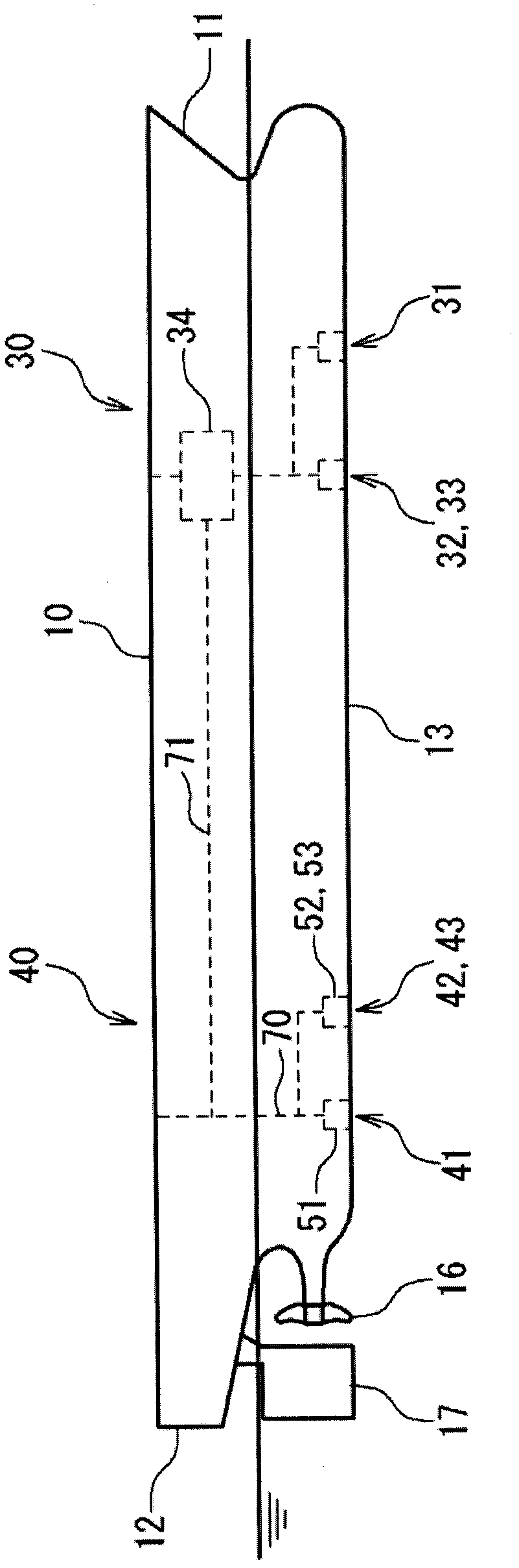
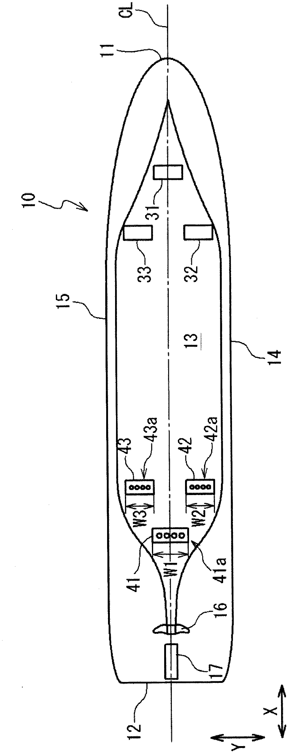
[0033] refer to Figure 1A , the frictional resistance reducing type ship according to the first embodiment of the present invention has a hull 10 , an air injection unit 30 provided in the hull 10 , and an air recovery device 40 provided in the hull 10 . The hull 10 has a bow 11 , a stern 12 , a bottom 13 , propellers 16 and a rudder 17 .

[0034] The air injection unit 30 has air injection ports 31 - 33 provided on the bow 11 side of the ship bottom 13 , and a compressor or blower 34 .

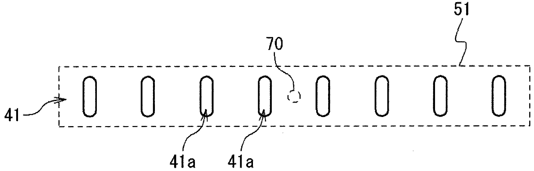
[0035] The air recovery device 40 has air recovery ports 41 - 43 provided on the stern 12 side of the ship bottom 13 , air recovery chambers 51 - 53 , and a flow path 70 . The air recovery chambers 51-53 have a gas-liquid separation function. For example, the gas-liquid separation chamber disclosed in Japanese Patent Publication JP 2009-248831A can be applied to the air recovery chambers 51-53. When the air recovery chambers 51-53 have a gas-liquid separation function, they may be referred...

no. 2 example

[0047] refer to image 3 , the frictional resistance reduction type ship according to the second embodiment of the present invention is the same as the frictional resistance reduction type ship according to the first embodiment except the following points. The port side air recovery port 42 and the starboard side air recovery port 43 are formed in a strip shape extending obliquely with respect to the ship's length direction X so that the respective ends of the port side air recovery port 42 and the starboard side air recovery port 43 on the stern 12 side are closer to each other. centerline CL, and the other end on the bow 11 side is away from the centerline CL.

[0048] According to the present embodiment, the ends of the port side air recovery port 42 and the starboard side air recovery port 43 closer to the propeller 16 are positioned near the center line CL, thereby preventing air bubbles from being drawn into the propeller 16 .

no. 3 example

[0050] refer to Figure 4 , a frictional resistance reduction type ship according to a third embodiment of the present invention will be described. The frictional resistance reduction type ship according to the present embodiment is the same as the frictional resistance reduction type ship according to the first embodiment except for the following points. In this embodiment, the air recovery chambers 51 - 53 have no gas-liquid separation function, and the air recovery device 40 has a single gas-liquid separation chamber 55 . Seawater containing air bubbles flows into the gas-liquid separation chamber 55 through the air recovery ports 41-43. The gas-liquid separation chamber 50 separates air from seawater. Air is exhausted to atmosphere through flow passage 70 as the separated product or supplied to compressor or blower 34 through flow passage 71 .


PUM


Abstract

Provided is a ship encountering less frictional resistance. The ship blows air into the water to reduce the frictional resistance between the hull of the ship and the water and prevents bubbles from being entrained in a propeller (16) of the ship while the strength of the hull is maintained. An air blowing device (30) blows air into the water through air blow ports (31-33) formed in a ship bottom (13). An air collection device (40) collects air in the hull through first to third air collection ports (41-43). The propeller (16) is disposed on the centerline (CL) of the ship. The first air collection port (41) is formed across the centerline (CL). The second air collection port (42) is formed on the port side of the centerline (CL) so that the second air collection port (42) protrudes further to the port side than the first air collection port (41). The third air collection port (43) is formed on the starboard side of the centerline (CL) so that the third air collection port (43) protrudes further to the starboard side than the first air collection port (41). The second and third air collection ports (42-43) are closer to the bow side of the ship than the first air collection port (41). Each of the first to third air collection ports (41-43) comprises a plurality of air collection holes (41a-43a).

Description

technical field [0001] The present invention relates to a frictional resistance reduction type ship in which the frictional resistance of a hull is reduced by spraying air into water. Background technique [0002] It is known to reduce the frictional resistance of the hull of a ship by covering the bottom surface of the ship with a stream of air bubbles while sailing. When air bubbles are drawn into the thruster, problems such as low propulsion efficiency and increase in vibratory force of the thruster arise. [0003] Japanese Patent Publication JP 2009-248831A discloses an air bubble entrapment prevention device for preventing air bubbles from being entangled in a propeller. This air bubble entrapment prevention device has an air bubble suction port provided in the ship bottom on the stern side, and a gas-liquid separation chamber. Seawater mixed with bubbles is brought into the gas-liquid separation chamber from the bubble suction port, and is separated into air and seaw...

Claims


Application Information

Patent Timeline
Patent Type & Authority Applications(China)
IPC IPC(8): B63B1/38B63H5/07
CPCB63B1/38Y02T70/122B63B2001/387Y02T70/10
Inventor 川北千春小段洋一郎高野真一
Owner MITSUBISHI SHIPBUILDING CO LTD
Why Eureka
Try Eureka