The second and fourth precast concrete parts and the joining method of the precast concrete parts

A technology of precast concrete and joining method, which is applied in the processing of building materials, construction, building structure, etc., can solve the problems of increased burden, complicated manufacture of PCa parts, and increased cost, and achieves the effect of simple structure

Active Publication Date: 2018-10-02
FUJITA CO LTD
View PDF4 Cites 0 Cited by
  • Summary
  • Abstract
  • Description
  • Claims
  • Application Information

AI Technical Summary

Problems solved by technology

[0008] However, in the method adopting the above-mentioned structure, it is necessary to pass the above-mentioned Figure 23 For the joint of the PCa wall or the PCa column and the PCa wall of the same layer, in order to carry out the connection work of the above-mentioned steel bars, it is necessary to ensure a certain interval or more after the above-mentioned steel bars are connected. Concrete is poured at the construction site, so there is a problem that it is difficult to achieve complete prefabrication, and there is also a problem that the work burden on the site increases and the cost increases.
[0009] In addition, when reinforcing bars are protrudingly formed on the side surfaces of the above-mentioned PCa members in advance, it is also possible to form the above-mentioned protruding reinforcing bars into a shape that is closed to each other at the ends, or to form the above-mentioned bars by bending them at 90 degrees. The protruding steel bars make the structure more complicated, and the manufacturing of PCa parts in the factory becomes more complicated, which becomes an important reason for the cost increase
[0010] In addition, in the case where reinforcing bars are protrudingly formed on the side surfaces of the PCa member as described above, since these protruding reinforcing bars may have complicated structures at the ends as described above, the protruding reinforcing bars may be damaged during transportation. There is also the problem of deformation and bending in the middle, because the steel bar is protruding, so there is still danger, and there are also problems such as the place where it needs to be kept.

Method used


Image

  • The second and fourth precast concrete parts and the joining method of the precast concrete parts
  • The second and fourth precast concrete parts and the joining method of the precast concrete parts
  • The second and fourth precast concrete parts and the joining method of the precast concrete parts

Examples


Embodiment Construction

[0062] Hereinafter, a precast concrete part provided with a joining member and a precast concrete part joining method using the precast concrete part according to the present invention will be described with reference to the drawings. In addition, in the following description, the same reference numerals are used for the same constituent elements, even for constituent elements that can be adopted in other forms, and overlapping descriptions, structures, and expressions may be partially omitted. In addition, for convenience of description, the size, ratio, etc. of each component shown in the drawings may differ from actual ones.

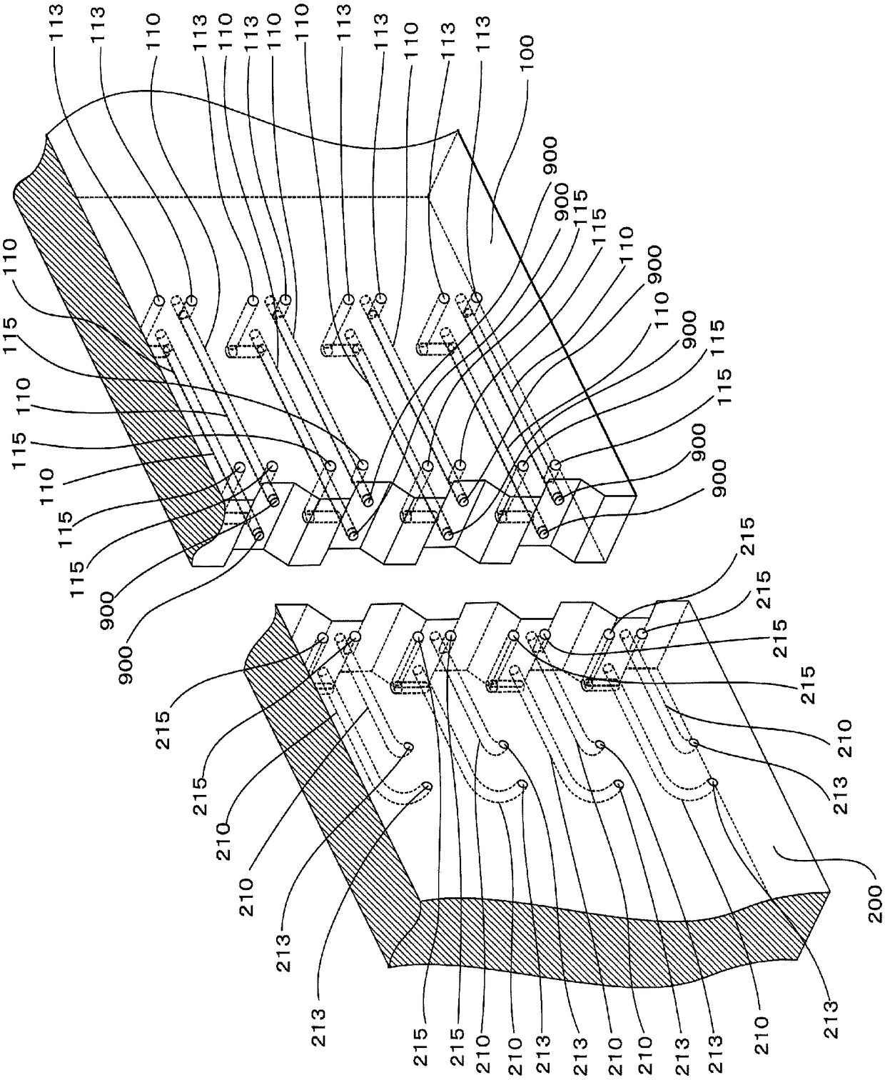
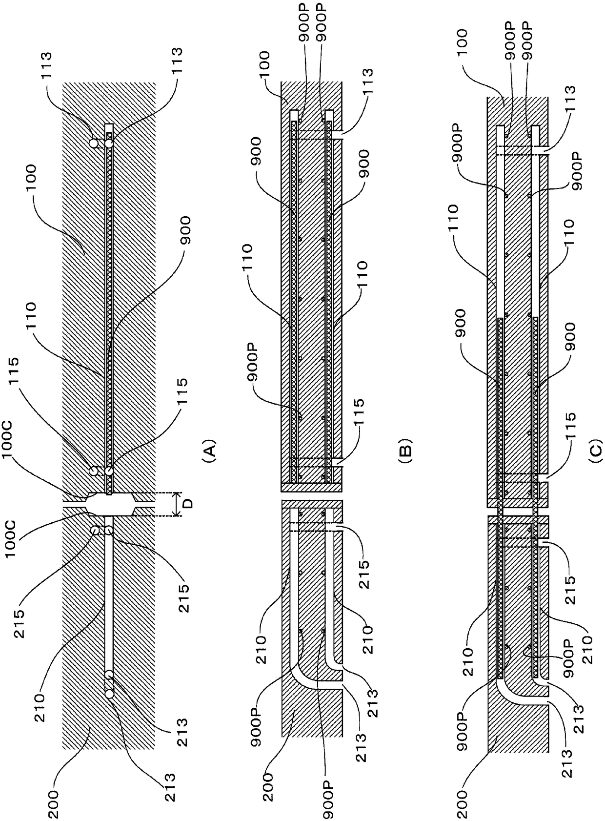
[0063] In the present invention, as figure 1 and figure 2 As shown, for example, a first tubular member 110 is preliminarily installed in a first PCa member 100 such as an anti-seismic wall, and a steel bar 900 is movably packed into the inside of the tubular member 110, thereby, the first PCa member can be In 100, the first PCa member 100 with st...


PUM


Abstract

[Problem] To allow a PCa member to be easily connected by using a comparatively simple structure and without projecting reinforcing bar in advance from a side face of the PCa member while fully using precast concrete and eliminating onsite cast-in-situ concrete to the extent possible. [Solution] A precast concrete member comprising a connection means, wherein the connection means is a tubular member provided in the precast concrete member and a reinforcing bar provided in the tubular member so as to be able to move, and the reinforcing bar is configured so as to be pulled from a side face of the precast concrete member during connection.

Description

technical field [0001] The present invention relates to a precast concrete part including a joining member and a precast concrete part joining method using the precast concrete part. Background technique [0002] Conventionally, as a labor-saving construction method for buildings, precast concrete (hereinafter, sometimes referred to as "PCa") components have been used. Such PCa parts are manufactured in a factory, so compared with the case of installing steel bars and pouring concrete at the construction site, since it can be cured without being affected by weather such as rain, the quality is stable, and there is a formwork at the construction site. Or reinforcement workers can save labor, and the construction method is simple and can shorten the construction period and many other advantages. It is widely used in columns or beams, (seismic) walls, floors or balconies of buildings. [0003] And, in the case of joining such PCa parts to each other, for example, using Figure...

Claims


Application Information

Patent Timeline
Patent Type & Authority Patents(China)
IPC IPC(8): E04B1/41E04B1/04E04G21/12
CPCE04B1/61
Inventor 三瓶昭彦
Owner FUJITA CO LTD
Why Eureka
Try Eureka