

Filter medium for air filters, air filter, air purifier provided with air filter and air purifier with humidifying function
An air purification device and air filter technology, which is applied to membrane filters, filtration separation, lighting and heating equipment, etc., can solve problems such as reduced productivity
- Summary
- Abstract
- Description
- Claims
- Application Information
AI Technical Summary
Problems solved by technology
Method used
Image

Examples
Embodiment approach 1
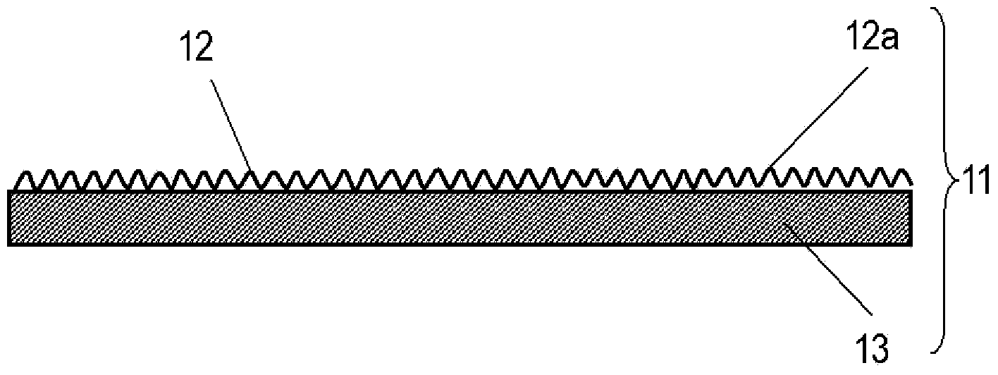
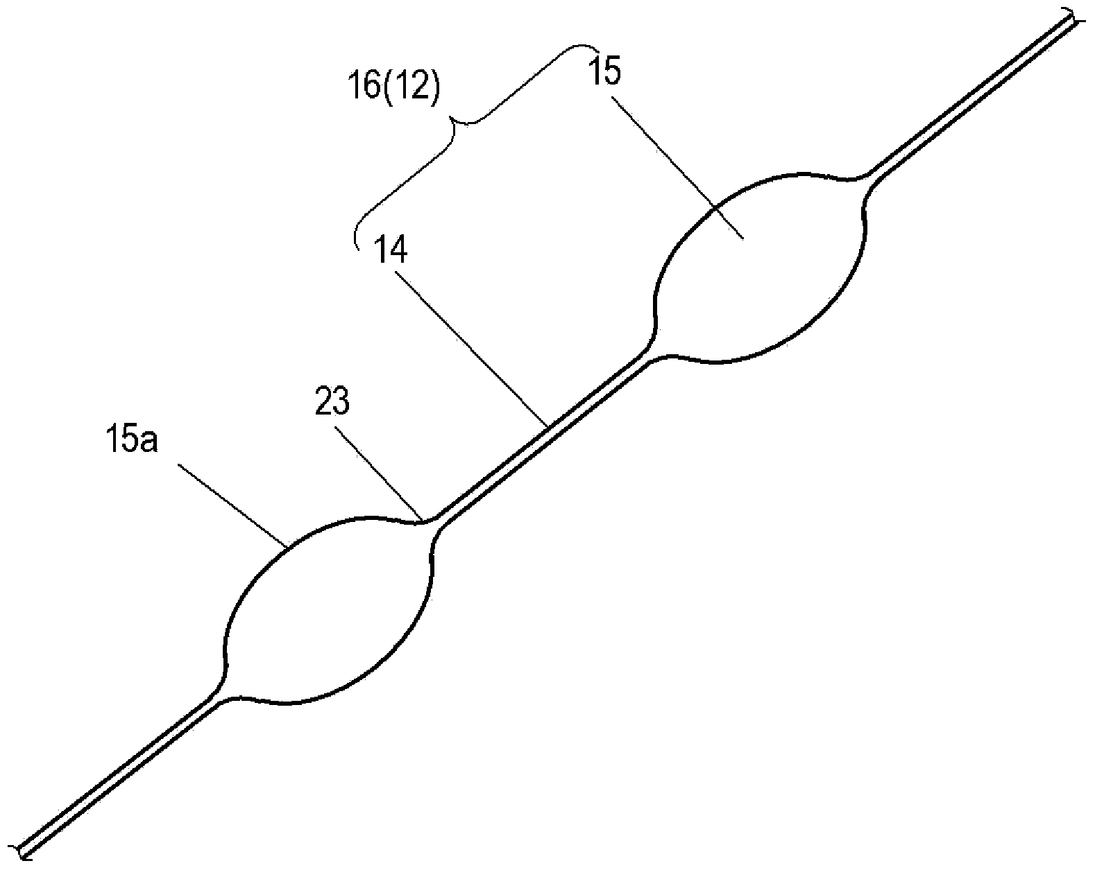
[0042] figure 1 It is a schematic sectional view showing the air filter element according to Embodiment 1 of the present invention, figure 2 is an enlarged view of the beaded fibers of the air filter element. Such as figure 1 and figure 2 As shown, the air filter element 11 includes: a fine fiber layer 12a composed of fine fibers 12; and a substrate 13 for holding the fine fiber layer 12a. The thin fibers 12 have an average fiber diameter of 100 nm to 1000 nm, and are bead-shaped fibers 16 composed of fibers 14 and beads 15 . The thin fibers 12 and the base material 13 are bonded by melting the surface layer 15a of the bead.
[0043] Such as figure 2 As shown, the beads 15 of fine fibers 12 are spindle-shaped. Cutting of the boundary between the fiber 14 and the bead 15 can be prevented by making the boundary 23 between the bead 15 and the fiber a curved line. As a result, the filter performance of the air filter 11 can be stably obtained.
[0044] The fine fibers...
Embodiment approach 2
[0056] In the second embodiment of the present invention, the same components as those in the first embodiment are denoted by the same reference numerals, and detailed description thereof will be omitted. Figure 5 It is a schematic cross-sectional view showing the air filter element according to Embodiment 2 of the present invention.
[0057] Such as Figure 5 As shown, the air filter element 11a includes: a thin fiber layer 12a composed of fine fibers 12; a base material 13; and a protective layer 17 for protecting the thin fibers 12. The thin fibers 12 and the protective layer 17 are bonded by melting the surface layer 15a of the bead.
[0058] In such an air filter element 11a, damage to the fine fibers 12 due to external contact can be prevented. In addition, the beads 15 become flattened, and the bonded areas between the thin fibers 12 and the substrate 13 and between the thin fibers 12 and the protective layer 17 increase. Therefore, compared with the case of using t...
Embodiment )
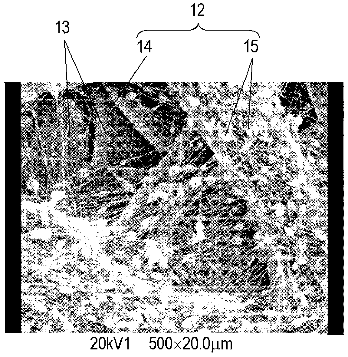
[0062] A solution obtained by dissolving 20 wt% of PES (polyethersulphone: polyethersulfone) in DMAc (dimethylacetamide: dimethylacetamide) was electrospun to obtain figure 2 Beaded fibers 16 consisting of fibers 14 and beads 15 are shown. At this time, air-permeable cellophane is pasted on the ground plate, so the cross-section becomes figure 1 structure shown.
[0063] Cover the non-woven fabric sheet that contains low-melting point resin material as protective layer 17 on the fine fiber face of air filter filter element 11 obtained in this way, with about 800cm 2 / min at a speed of 120°C. Table 1 shows the pressure loss when air passes through the air filter element 11a at a face velocity of 5.3 cm / sec when two types of samples made of different nonwoven fabric sheets were produced. The pressure loss of the two types of samples increased slightly, but the If the increase range is within 5%, there is no meaningful difference as the air filter element 11a, and it was con...
PUM
| Property | Measurement | Unit |
|---|---|---|
| diameter | aaaaa | aaaaa |
| softening point | aaaaa | aaaaa |
| size | aaaaa | aaaaa |
Abstract
Description
Claims
Application Information