Valve, gas control device, and sphygmomanometer

A control device and gas technology, applied in the field of sphygmomanometers, can solve the problems of direct bonding of large containers with a large amount of air, and the second plate cannot have a large bonding area, etc., to achieve the effect of large bonding area

Active Publication Date: 2018-11-23
MURATA MFG CO LTD
View PDF7 Cites 9 Cited by
  • Summary
  • Abstract
  • Description
  • Claims
  • Application Information

AI Technical Summary

Problems solved by technology

Therefore, the second plate cannot have a large joint area
Therefore, in the gas control device of Patent Document 1, there is a problem that it is difficult to directly join a large container capable of containing a large amount of air to the second plate.

Method used


Image

  • Valve, gas control device, and sphygmomanometer
  • Valve, gas control device, and sphygmomanometer
  • Valve, gas control device, and sphygmomanometer

Examples


other Embodiment approach

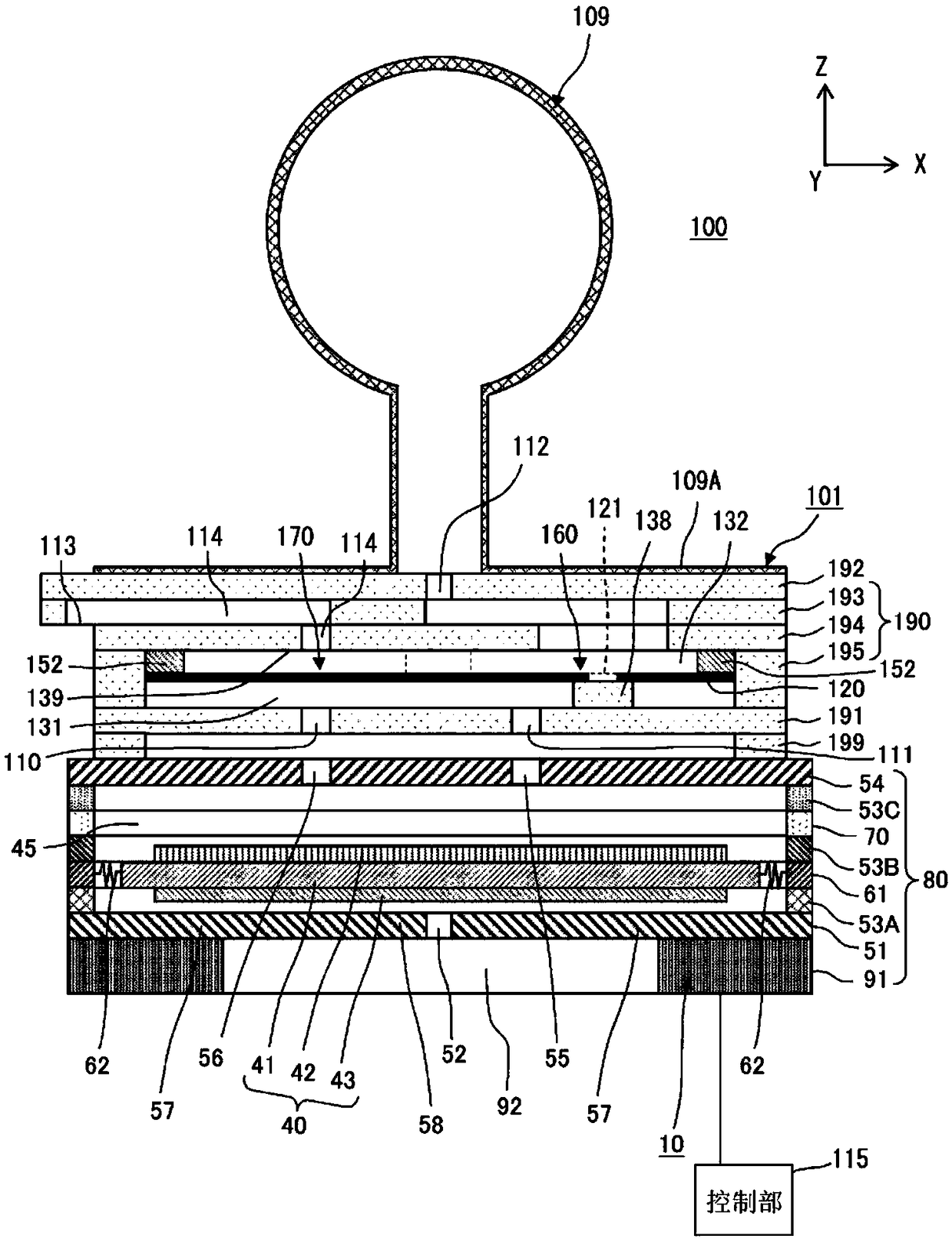
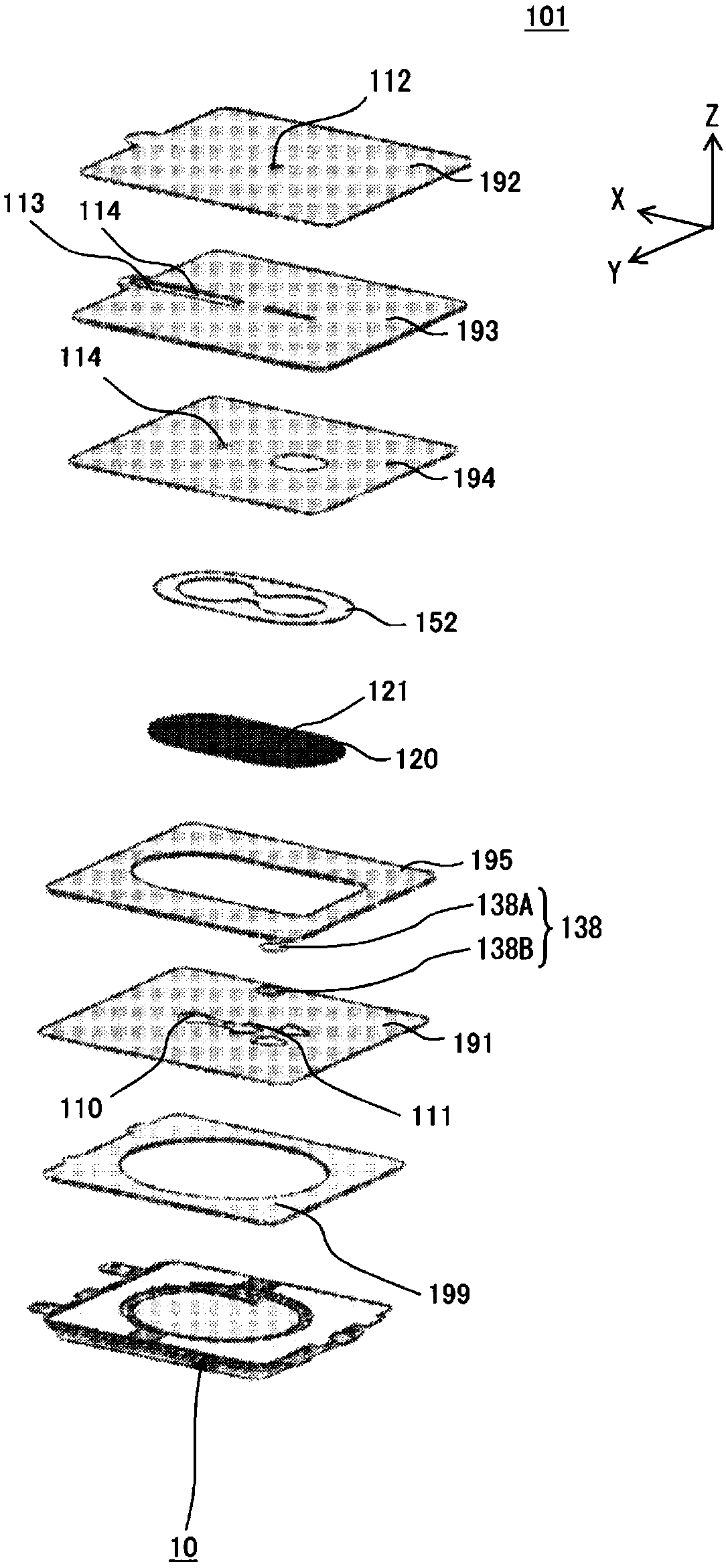
[0100] In addition, in the foregoing embodiments, air is used as the gas, but it is not limited thereto. In practice, as the gas, a gas other than air can also be used.

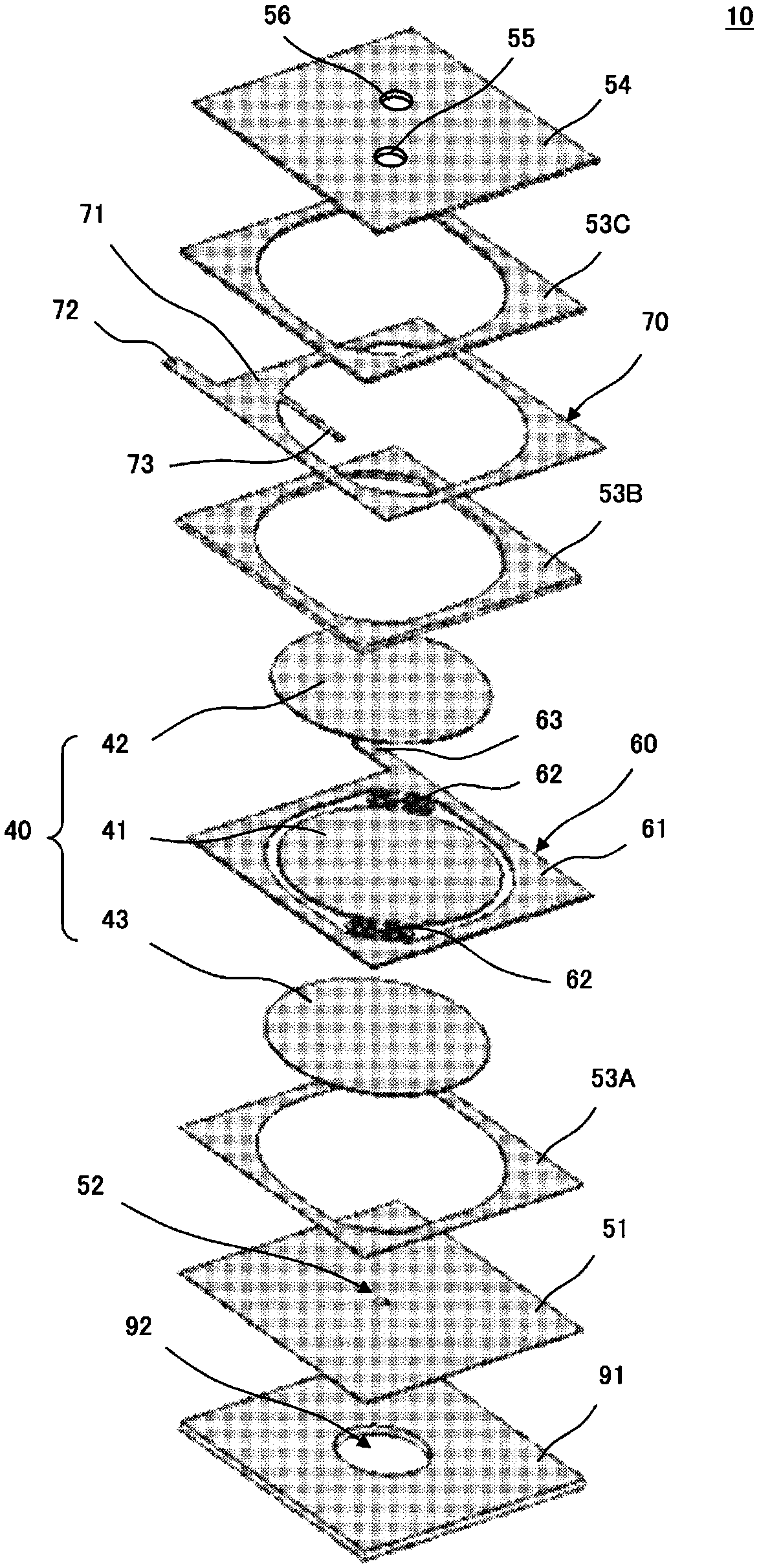
[0101] In addition, the pump 10 of the above-mentioned embodiment includes the actuator 40 that performs bending vibration in the unimorph type, but it may also include the actuator 40 that performs bending vibration in the bimorph type by attaching piezoelectric elements on both sides of the vibrating plate. the actuator.

[0102] In addition, although the pump 10 of the above-mentioned embodiment includes the actuator 40 that bends and vibrates due to expansion and contraction of the piezoelectric element 42, the present invention is not limited thereto. For example, an actuator that performs bending vibration by electromagnetic drive may be provided.

[0103] In addition, although the pump 10 of the above-mentioned embodiment is equipped with the discharge hole 55 and the discharge hole 56, it is not lim...


PUM


Abstract

This gas control device (100) comprises a pump (10), a valve (101), a cuff (109), and a control unit (115). The valve (101) comprises: a first plate (191) provided with a first ventilating hole (110)and a first ventilating hole (111); a flowpath-forming plate (190) provided with an exhaust hole (113) and an exhaust flowpath (114); a second plate (192) provided with a second ventilating hole (112); and a trim plate (199). The valve (101) and the cuff (109) are connected by joining an armband rubber tube (109A) of the cuff (109) to the periphery of the second ventilating hole (112) in the second plate (192) using an adhesive. The exhaust hole (113) is open to the atmosphere. The pump (10) has a pump housing (80) to which a discharge hole (55) and a discharge hole (56) are provided. The upper surface of the pump housing (80) is joined to the bottom surface of the trim plate (199) of the valve (101).

Description

technical field [0001] One embodiment of the present invention relates to a valve for regulating the flow of gas, a gas control device, and a sphygmomanometer. Background technique [0002] Conventionally, various studies have been conducted on gas control devices that control the flow of gas. For example, Patent Document 1 discloses a gas control device including a piezoelectric pump, a valve, and a cuff. The piezoelectric pump has a suction hole and a discharge hole. The valve includes: a first plate having a first vent hole; and a second plate having a second vent hole and an exhaust hole. The second plate has a nozzle, the interior of which constitutes a second vent hole. The discharge hole of the piezoelectric pump is connected to the first vent hole of the valve. The cuff is installed on the nozzle of the valve, and the second vent hole of the valve is connected to the cuff. [0003] Patent Document 1: International Publication 2016 / 63710 Pamphlet [0004] In rec...

Claims


Application Information

Patent Timeline
Patent Type & Authority Applications(China)
IPC IPC(8): F04B45/04A61B5/0225
CPCA61B5/0225F16K7/17A61B5/02233A61B5/0235F04B45/047F16K7/00
Inventor 川村宪一郎儿玉幸治成田幸辅阿知波宽基竹村洋
Owner MURATA MFG CO LTD
Why Eureka
Try Eureka